Index
Introduction
The KY-020 Tilt Switch is a simple sensor used to detect the orientation or tilt of an object. It contains a conductive ball inside that moves when the sensor is tilted, opening or closing the circuit. The ESP32 can read the sensor’s digital output and determine whether the module is tilted. Tilt switches are commonly used in security systems, motion detection projects, and orientation sensing applications. In this tutorial, we’ll interface a KY-020 Tilt Switch with the ESP32 and monitor its status through the Serial Monitor.
Required Components
- ESP32 Board
- KY-020 Tilt Switch Module
- Jumper Wires
- Breadboard
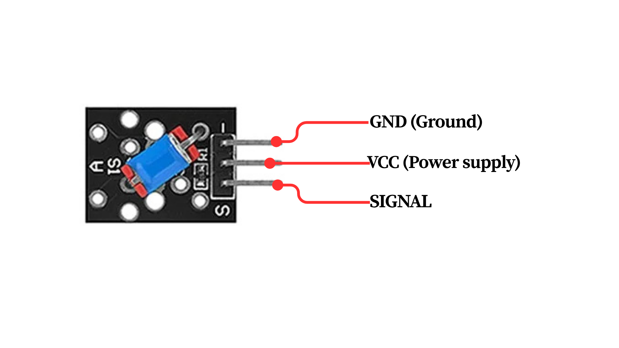
Pinout
Circuit Diagram / Wiring
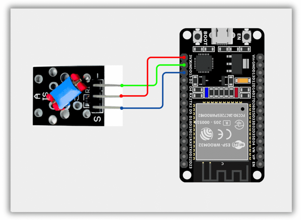
- KY-020 VCC → 3.3V (ESP32)
- KY-020 GND → GND (ESP32)
- KY-020 OUT → GPIO 15 (ESP32)
Code / Programming
/*
  Filename: ol_tilt_switch.ino
  Description: Reads KY-020 Tilt Switch status and prints result via Serial Monitor
  Author: www.oceanlabz.in
  Modification: 1/4/2025
*/

#define TILT_SENSOR_PIN 15

void setup() {
  Serial.begin(115200);
  pinMode(TILT_SENSOR_PIN, INPUT);
}

void loop() {
  int tiltState = digitalRead(TILT_SENSOR_PIN);

  if (tiltState == LOW) {
    Serial.println("Tilt Detected");
  } else {
    Serial.println("Normal Position");
  }

  delay(500);
}
Explanation
- The TILT_SENSOR_PIN reads the digital output from the KY-020 Tilt Switch.
- When the sensor is tilted, the conductive ball inside moves and changes the circuit state.
- The ESP32 continuously monitors the sensor output and determines whether a tilt has occurred.
- The current sensor status is displayed on the Serial Monitor.
Troubleshooting
- Ensure that the KY-020 module is powered correctly (VCC to 3.3V and GND to GND) and that the output pin is connected to GPIO 15.
- If the sensor does not detect tilting, try changing the module orientation and testing again.
- If the readings fluctuate, ensure the sensor is mounted securely and check the wiring connections.
- If no messages appear in the Serial Monitor, verify that the correct COM port and ESP32 board are selected in the Arduino IDE.