Index
Introduction
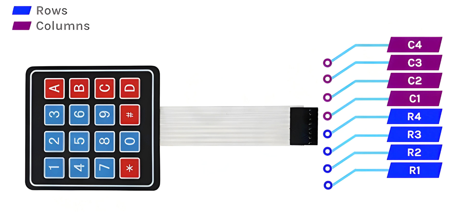
The 4×4 Membrane Keypad is a simple user interface device with 16 keys arranged in 4 rows and 4 columns.
Each key press connects a unique row-column pair, which the ESP32 can detect using digital input pins.
It’s ideal for projects requiring password input, menu navigation, or number entry.
In this tutorial, we’ll learn how to connect the 4×4 keypad to an ESP32 and read key presses using the Arduino IDE.
Required Components
- ESP32 Board
- 4×4 Keypad
- Jumper wires
- Breadboard (optional)
Pinout
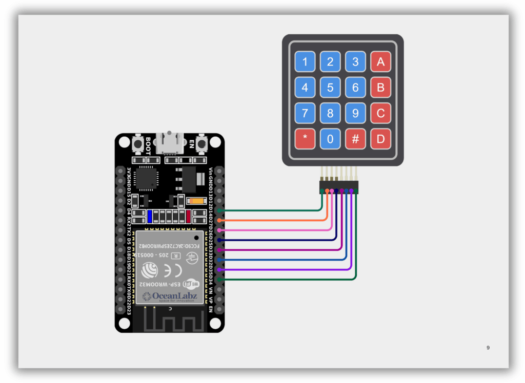
Circuit Diagram / Wiring
- Keypad Column 4 → 34 (ESP32)
- Keypad Column 3 → 35 (ESP32)
- Keypad Column 2 → 32 (ESP32)
- Keypad Column 1 → 33 (ESP32)
- Keypad Row 4 → 25 (ESP32)
- Keypad Row 3 → 26 (ESP32)
- Keypad Row 2 → 27 (ESP32)
- Keypad Row 1 → 14 (ESP32)
Code / Programming
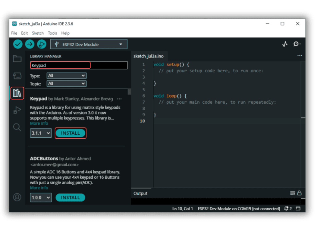
- Install Required Library (via Arduino Library Manager).
- Go to the “Libraries” tab on the left-hand side of the screen.
- Click on the “Library Manager” button (book icon) at the top of the Libraries tab.
- In the Library Manager window, type “Keypad” in the search bar.
- Locate the “Keypad” library click on the “Install” button next to it.
- Wait for the library to be installed, and you’re ready to use the Keypad library in your projects.
/*
Filename: esp32_keypad_input.ino
Description: Reads input from a 4x4 keypad and prints pressed keys to the Serial Monitor
Author: www.oceanlabz.in
Modification: 1/4/2025
*/


#include <Keypad.h>

const byte ROWS = 4;
const byte COLS = 4;

char keys[ROWS][COLS] = {
  {'1','2','3','A'},
  {'4','5','6','B'},
  {'7','8','9','C'},
  {'*','0','#','D'}
};

byte rowPins[ROWS] = {14, 27, 26, 25}; // Connect to R1-R4
byte colPins[COLS] = {33, 32, 35, 34}; // Connect to C1-C4

Keypad keypad = Keypad(makeKeymap(keys), rowPins, colPins, ROWS, COLS);

void setup() {
  Serial.begin(115200);
}

void loop() {
  char key = keypad.getKey();

  if (key) {
    Serial.print("Key Pressed: ");
    Serial.println(key);
  }
}
Explanation
- A 4×4 keypad has 16 keys arranged in a matrix of 4 rows and 4 columns.
- Each key press connects a specific row and column, which the ESP32 detects using digital I/O pins.
- The
Keypadlibrary scans the matrix and returns the character of the pressed key.
Troubleshooting
- Ensure keypad pins are connected in the correct row/column order to the ESP32.
- Avoid using boot-related GPIOs like GPIO0, GPIO2, or GPIO15 for keypad connections.
- If no key press is detected, check for loose wires, incorrect wiring, or wrong pin numbers in code.
Project 1: ESP32 Keypad Display Interface with OLED Feedback
Introduction
This project showcases a digital keypad interface using ESP32 and an OLED display.
When a key is pressed on the 4×4 keypad, the input is instantly shown on the OLED screen.
It provides real-time feedback and can be extended for password entry or menu selection.
Ideal for interactive systems, smart locks, and user input-based IoT applications.
Required Components
- ESP32 Board
- OLED Display
- 4×4 Keypad
- Jumper wires
- Breadboard
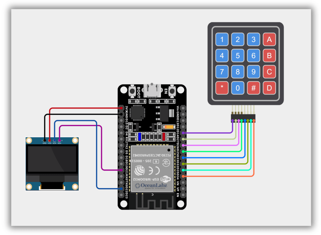
Circuit Diagram / Wiring
- Keypad Column 4 → 34 (ESP32)
- Keypad Column 3 → 35 (ESP32)
- Keypad Column 2 → 32 (ESP32)
- Keypad Column 1 → 33 (ESP32)
- Keypad Row 4 → 25 (ESP32)
- Keypad Row 3 → 26 (ESP32)
- Keypad Row 2 → 27 (ESP32)
- Keypad Row 1 → 14 (ESP32)
Code / Programming
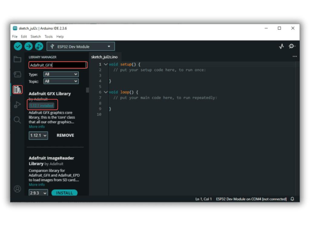
- Install Required Libraries (via Arduino Library Manager).
- Go to the “Libraries” tab on the left-hand side of the screen.
- Click on the “Library Manager” button (book icon) at the top of the Libraries tab.
- In the Library Manager window, type “Adafruit_GFX” in the search bar.
- Locate the “Adafruit_GFX” library click on the “Install” button next to it.
- Wait for the library to be installed, and you’re ready to use the Adafruit_GFX library in your projects.
- Repeat the process to download all the libraries.
/*
Filename: esp32_keypad_oled_display.ino
Description: Displays pressed keypad key on an OLED using ESP32 and 4x4 matrix keypad
Author: www.oceanlabz.in
Modification: 1/4/2025
*/


#include <Keypad.h>
#include <Wire.h>
#include <Adafruit_GFX.h>
#include <Adafruit_SSD1306.h>

// Define screen width and height
#define SCREEN_WIDTH 128
#define SCREEN_HEIGHT 64

// Create display object (use I2C address 0x3C)
Adafruit_SSD1306 display(SCREEN_WIDTH, SCREEN_HEIGHT, &Wire, -1);

// Define keypad rows and columns
const byte ROWS = 4;
const byte COLS = 4;

char keys[ROWS][COLS] = {
  {'1','2','3','A'},
  {'4','5','6','B'},
  {'7','8','9','C'},
  {'*','0','#','D'}
};

// Update to ESP32-compatible GPIO pins
byte rowPins[ROWS] = {14, 27, 26, 25};  // Connect to R1, R2, R3, R4
byte colPins[COLS] = {33, 32, 35, 34};   // Connect to C1, C2, C3, C4

// Create keypad object
Keypad keypad = Keypad(makeKeymap(keys), rowPins, colPins, ROWS, COLS);

void setup() {
  Serial.begin(115200);

  // Initialize OLED (optionally define SDA, SCL if not default)
  Wire.begin(21, 22);  // SDA, SCL
  if (!display.begin(SSD1306_SWITCHCAPVCC, 0x3C)) {
    Serial.println(F("SSD1306 allocation failed"));
    while (true); // Halt if OLED fails
  }

  // Show splash screen
  display.clearDisplay();
  display.setTextSize(1);
  display.setTextColor(WHITE);
  display.setCursor(30, 0);
  display.println("zintechideas");
  display.display();
  delay(1000);
  display.clearDisplay();
}

void loop() {
  char key = keypad.getKey();

  display.setTextSize(1);
  display.setTextColor(WHITE);
  display.setCursor(30, 0);
  display.println("zintechideas");

  if (key) {
    Serial.println(key);  // Debug key press in Serial Monitor

    display.setTextSize(3);
    display.setTextColor(WHITE);
    display.setCursor(55, 10);
    display.println(key);
    display.display();
    delay(1000);
    display.clearDisplay();
  }
}
Explanation
- A 4×4 matrix keypad is connected to the ESP32 to detect button presses.
- An SSD1306 OLED display shows the pressed key in real-time using the Adafruit GFX library.
- The project initializes the display and keypad in
setup()and continuously listens for key inputs inloop().
Troubleshooting
- No display output: Ensure the OLED is properly connected (I2C SDA to GPIO 21, SCL to GPIO 22 by default on ESP32).
- Keypad not responding: Check correct pin mapping and stable wiring of
rowPinsandcolPins. - Garbled display: Ensure you’re using the correct I2C address (
0x3C) and the OLED size matches your screen (typically 128×64).