Index
Introduction
In this tutorial, we are using a pulse sensor with ESP32 to measure heart rate.
The sensor detects blood flow changes in the fingertip using infrared light.
The ESP32 reads the analog signal and processes it to determine real-time heartbeats.
It’s commonly used in DIY health monitors and wearable fitness projects.
Required Components
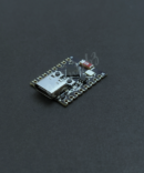
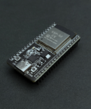
- ESP32 Board
- Pulse Sensor
- Jumper wires
- Breadboard
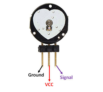
Pinout
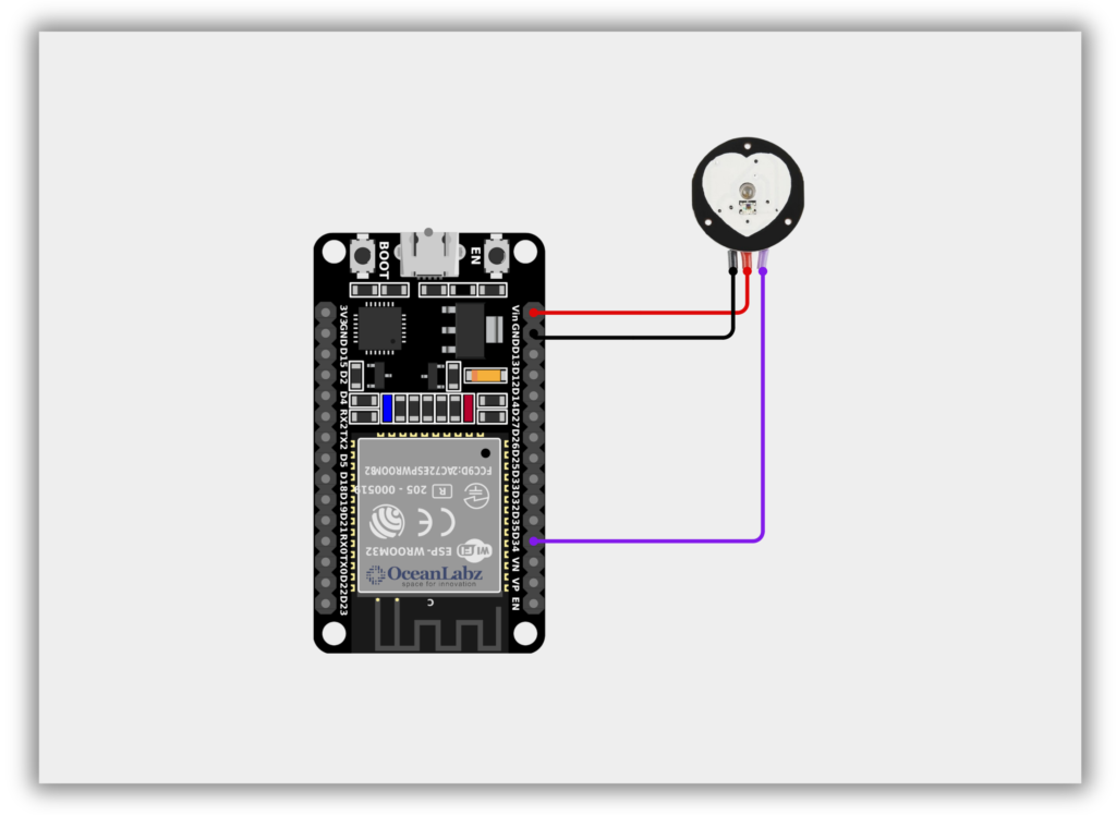
Circuit Diagram / Wiring
- Pulse Sensor VCC → VIN/5V (ESP32)
- Pulse Sensor GND → GND (ESP32)
- Pulse Sensor Signal → 34 (ESP32)
Code / Programming
/*
  Filename: esp32_pulse_sensor_read.ino
  Description: Reads analog pulse signal from a pulse sensor using ESP32 and prints to Serial Monitor.
  Author: www.oceanlabz.in
  Modification: 1/4/2025
*/


const int pulsePin = 34; // Pulse sensor connected to GPIO34 (ADC1)
int signal = 0;          // Variable to store pulse value

void setup() {
  Serial.begin(115200); // Use higher baud rate for ESP32
  Serial.println("Pulse Sensor Initialized");
}

void loop() {
  signal = analogRead(pulsePin);   // Read analog signal from pulse sensor
  Serial.println(signal);          // Print pulse value to Serial Monitor
  delay(10);                       // Small delay for stable reading
}
Explanation
- The pulse sensor detects blood flow changes in your fingertip using infrared light.
- The ESP32 reads this data via analog input (e.g., GPIO34) to monitor real-time heart activity.
- The signal can be visualized using the Serial Plotter to identify heartbeats clearly.
Troubleshooting
- If you get flat or noisy readings, ensure firm, stable finger contact and avoid movement.
- Use ADC1 pins only (GPIO32–GPIO39) for reliable analog readings on ESP32.
- If the Serial Monitor shows zero or static values, check wiring and sensor orientation.
Project 1: Heart Rate Monitor with OLED
Introduction
This project is a heart rate monitoring system using an ESP32, a pulse sensor, and a 128×64 OLED display.
It detects heartbeat signals from a fingertip and calculates the Beats Per Minute (BPM).
Real-time heart rate data is shown on the OLED screen along with a live waveform graph.
An LED blinks with each heartbeat, providing visual feedback during measurement.
Required Components
- ESP32 Board
- Pulse Sensor
- OLED Display
- Jumper wires
- Breadboard
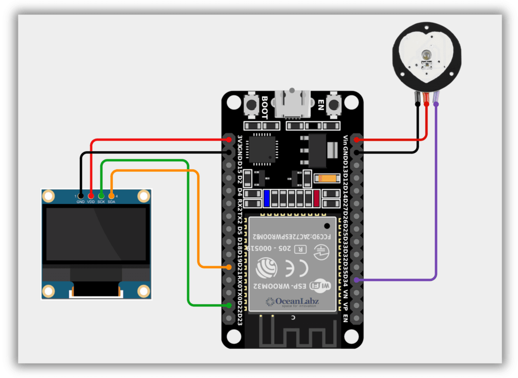
Circuit Diagram / Wiring
- Pulse Sensor VCC → VIN/5V (ESP32)
- Pulse Sensor GND → GND (ESP32)
- Pulse Sensor Signal → 34 (ESP32)
- OLED VCC → 3.3V (ESP32)
- OLED GND → GND (ESP32)
- OLED SDA → Pin 21 (ESP32)
- OLED SCK → Pin 22 (ESP32)
Code / Programming
/*
  Filename: esp32_pulse_oled_graph_bpm.ino
  Description: Displays real-time pulse waveform and BPM on OLED using ESP32 and Pulse Sensor.
  Author: www.oceanlabz.in
  Modification: 1/4/2025
*/


1#include <SPI.h>
#include <Wire.h>
#include <Adafruit_GFX.h>
#include <Adafruit_SSD1306.h>

#define SCREEN_WIDTH 128
#define SCREEN_HEIGHT 64
#define OLED_RESET     -1
Adafruit_SSD1306 display(SCREEN_WIDTH, SCREEN_HEIGHT, &Wire, OLED_RESET);

unsigned long previousMillisGetHR = 0;
unsigned long previousMillisResultHR = 0;

const long intervalGetHR = 20;
const long intervalResultHR = 10000;

int PulseSensorSignal;
const int PulseSensorHRWire = 34; // Use GPIO34 (VP) for analog input on ESP32
int UpperThreshold = 550;
int LowerThreshold = 500;

int cntHB = 0;
boolean ThresholdStat = true;
int BPMval = 0;

int x = 0, y = 0, lastx = 0, lasty = 0;

const unsigned char Heart_Icon [] PROGMEM = {
  0x00, 0x00, 0x18, 0x30, 0x3c, 0x78, 0x7e, 0xfc, 0xff, 0xfe, 0xff, 0xfe, 0xee, 0xee, 0xd5, 0x56,
  0x7b, 0xbc, 0x3f, 0xf8, 0x1f, 0xf0, 0x0f, 0xe0, 0x07, 0xc0, 0x03, 0x80, 0x01, 0x00, 0x00, 0x00
};

void setup() {
  Serial.begin(115200);

  if(!display.begin(SSD1306_SWITCHCAPVCC, 0x3C)) {
    Serial.println(F("SSD1306 allocation failed"));
    while(1);
  }

  display.display();
  delay(1000);

  display.clearDisplay();
  display.setTextSize(1);
  display.setTextColor(WHITE);
  display.setCursor(0, 12);
  display.print("     Please wait");
  display.setCursor(0, 22);
  display.print("     10  seconds");
  display.setCursor(0, 32);
  display.print("       to get");
  display.setCursor(0, 42);
  display.print(" the Heart Rate value");
  display.display();
  delay(3000);

  display.clearDisplay();
  display.drawBitmap(0, 47, Heart_Icon, 16, 16, WHITE);
  display.drawLine(0, 43, 127, 43, WHITE);
  display.setTextSize(2);
  display.setCursor(20, 48);
  display.print(": 0 BPM");
  display.display();

  Serial.println("Please wait 10 seconds to get the BPM Value");
}

void loop() {
  GetHeartRate();
}

void GetHeartRate() {
  unsigned long currentMillisGetHR = millis();

  if (currentMillisGetHR - previousMillisGetHR >= intervalGetHR) {
    previousMillisGetHR = currentMillisGetHR;

    PulseSensorSignal = analogRead(PulseSensorHRWire);

    if (PulseSensorSignal > UpperThreshold && ThresholdStat == true) {
      cntHB++;
      ThresholdStat = false;
    }

    if (PulseSensorSignal < LowerThreshold) {
      ThresholdStat = true;
    }

    DrawGraph();
  }

  unsigned long currentMillisResultHR = millis();

  if (currentMillisResultHR - previousMillisResultHR >= intervalResultHR) {
    previousMillisResultHR = currentMillisResultHR;

    BPMval = cntHB * 6;
    Serial.print("BPM : ");
    Serial.println(BPMval);

    display.fillRect(20, 48, 108, 18, BLACK);
    display.drawBitmap(0, 47, Heart_Icon, 16, 16, WHITE);
    display.drawLine(0, 43, 127, 43, WHITE);
    display.setTextSize(2);
    display.setCursor(20, 48);
    display.print(": ");
    display.print(BPMval);
    display.print(" BPM");
    display.display();

    cntHB = 0;
  }
}

void DrawGraph() {
  if (x > 127) {
    display.fillRect(0, 0, 128, 42, BLACK);
    x = 0;
    lastx = 0;
  }

  int ySignal = PulseSensorSignal;
  if (ySignal > 850) ySignal = 850;
  if (ySignal < 350) ySignal = 350;

  int ySignalMap = map(ySignal, 350, 850, 0, 40);
  y = 40 - ySignalMap;

  display.writeLine(lastx, lasty, x, y, WHITE);
  display.display();

  lastx = x;
  lasty = y;
  x++;
}
Explanation
- The project reads heart rate data from an analog pulse sensor connected to ESP32 and visualizes it in real-time on a 128×64 OLED display.
- The BPM (Beats Per Minute) is calculated every 10 seconds based on threshold crossings of the pulse waveform.
- The OLED shows both a dynamic graph and the BPM reading along with a heart icon to indicate heartbeat activity.
Troubleshooting
- If the OLED display shows nothing, check the I2C wiring (SDA: GPIO21, SCL: GPIO22) and ensure the address is set to
0x3C. - If BPM stays at 0, ensure the pulse sensor is properly placed and try adjusting the threshold values.
- If random characters appear on the Serial Monitor, make sure the baud rate is set to 115200 in the Arduino IDE.