Index
Introduction
The Hall Sensor is a magnetic field detection sensor that operates based on the Hall Effect principle. It can detect the presence of a magnet and provide a digital output signal. The ESP32 can read this signal and determine whether a magnetic field is present. Hall sensors are commonly used in position sensing, speed detection, security systems, and automation projects. In this tutorial, we’ll interface a Hall Sensor with the ESP32 and monitor magnetic field detection through the Serial Monitor.
Required Components
- ESP32 Board
- Hall Sensor Module
- Jumper Wires
- Breadboard
Pinout
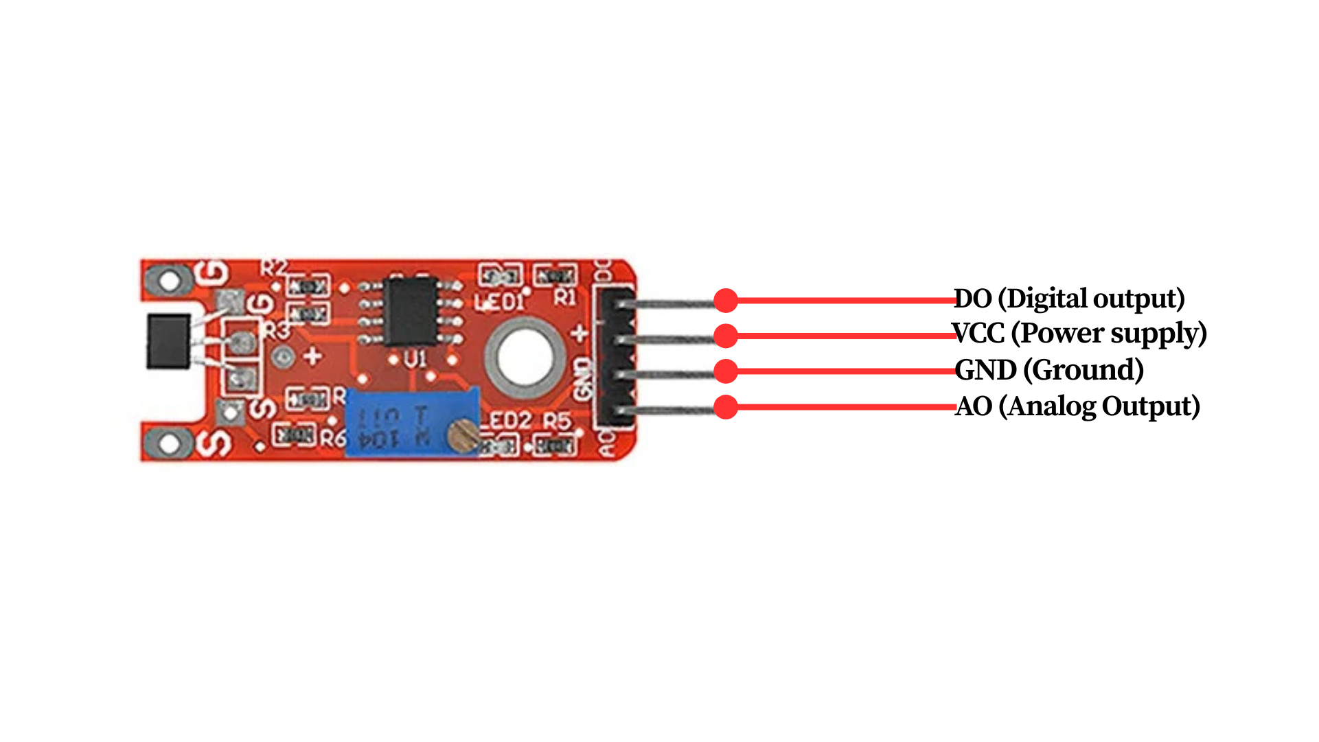
Circuit Diagram / Wiring
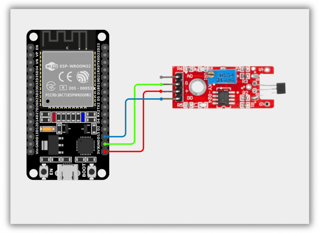
- Hall Sensor VCC → 3.3V (ESP32)
- Hall Sensor GND → GND (ESP32)
- Hall Sensor OUT → GPIO 15 (ESP32)
Code / Programming
/*
  Filename: ol_hall_sensor.ino
  Description: Reads Hall Sensor status and prints detection result via Serial Monitor
  Author: www.oceanlabz.in
  Modification: 1/4/2025
*/

#define HALL_SENSOR_PIN 15

void setup() {
  Serial.begin(115200);
  pinMode(HALL_SENSOR_PIN, INPUT);
}

void loop() {
  int hallState = digitalRead(HALL_SENSOR_PIN);

  if (hallState == LOW) {
    Serial.println("Magnet Detected");
  } else {
    Serial.println("No Magnet");
  }

  delay(500);
}
Explanation
- The HALL_SENSOR_PIN reads the digital output from the Hall Sensor.
- When a magnet comes near the sensor, the output changes state and the ESP32 detects the magnetic field.
- The ESP32 continuously monitors the sensor and displays the detection status on the Serial Monitor.
- The displayed message indicates whether a magnet is present near the sensor.
Troubleshooting
- Ensure that the Hall Sensor is powered correctly (VCC to 3.3V and GND to GND) and that the output pin is connected to GPIO 15.
- If the sensor does not detect the magnet, try bringing the magnet closer to the sensing area.
- If the readings are unstable, check the wiring connections and ensure a stable power supply.
- If no messages appear in the Serial Monitor, verify that the correct COM port and ESP32 board are selected in the Arduino IDE.