Index
Introduction
The MAX7219 8×8 LED Matrix module is a versatile component used to display text, numbers, and animations.
It simplifies the process of controlling individual LEDs in the 8×8 matrix using the MAX7219 chip.
This tutorial will guide you through connecting the matrix module to an ESP32 and programming it to display simple patterns, text, or scrolling messages.
Required Components
- ESP32 Board
- 8×8 LED Matrix Display Module
- Jumper wires
- Breadboard
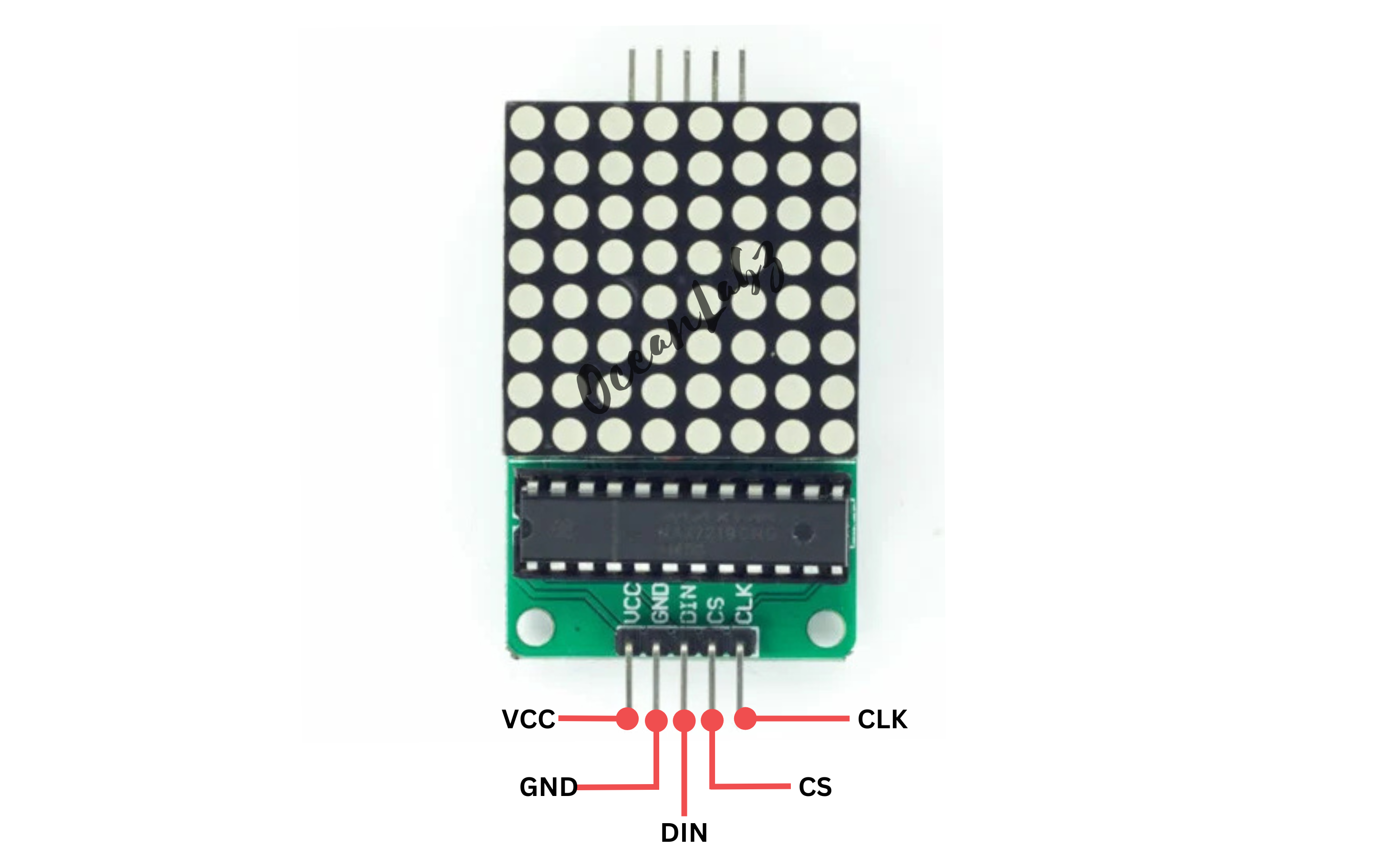
Pinout
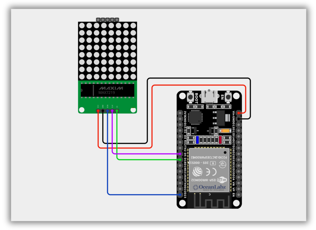
Circuit Diagram / Wiring
- VCC (LED Module) → VIN/5V (ESP32)
- GND (LED Module) → GND (ESP32)
- DIN (LED Module) → Pin 32(ESP32)
- CS (LED Module) → Pin 5(ESP32)
- CLK (LED Module) → Pin 18(ESP32)
Code / Programming
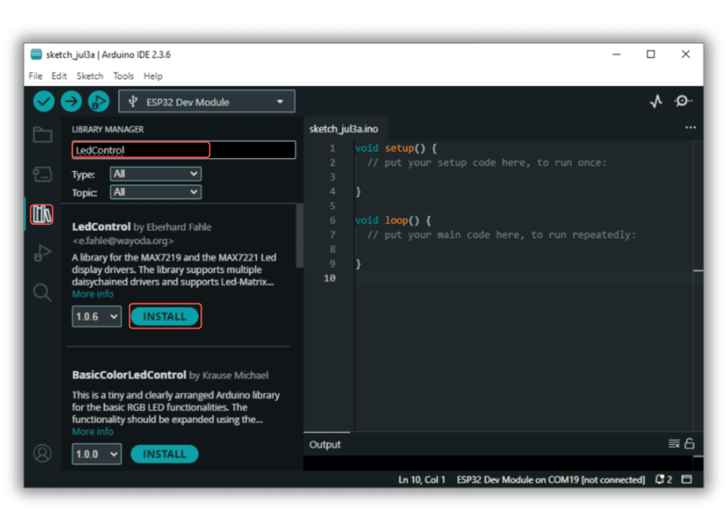
- Install Required Library (via Arduino Library Manager).
- Go to the “Libraries” tab on the left-hand side of the screen.
- Click on the “Library Manager” button (book icon) at the top of the Libraries tab.
- In the Library Manager window, type “LedControl” in the search bar.
- Locate the “LedControl” library click on the “Install” button next to it.
- Wait for the library to be installed, and you’re ready to use the LedControl library in your projects.
/*
  Filename: esp32_led_matrix_display.ino
  Description: Displays animated patterns (face, heart, smiley) on 8x8 LED matrix using MAX7219 and ESP32
  Author: www.oceanlabz.in
  Modified: 1/4/2025
*/


#include <SPI.h>

// ESP32 Pin Definitions
#define DATA_IN 23  // DIN (MOSI)
#define CLK     18  // CLK (SCK)
#define CS      5   // LOAD/CS

// MAX7219 registers
#define MAX7219_REG_NOOP        0x00
#define MAX7219_REG_DIGIT0      0x01
#define MAX7219_REG_DIGIT1      0x02
#define MAX7219_REG_DIGIT2      0x03
#define MAX7219_REG_DIGIT3      0x04
#define MAX7219_REG_DIGIT4      0x05
#define MAX7219_REG_DIGIT5      0x06
#define MAX7219_REG_DIGIT6      0x07
#define MAX7219_REG_DIGIT7      0x08
#define MAX7219_REG_DECODEMODE  0x09
#define MAX7219_REG_INTENSITY   0x0A
#define MAX7219_REG_SCANLIMIT   0x0B
#define MAX7219_REG_SHUTDOWN    0x0C
#define MAX7219_REG_DISPLAYTEST 0x0F

// Define the bitmaps
const uint8_t normalFace[8] = {
  B00111100,
  B01000010,
  B10100101,
  B10000001,
  B10000001,
  B10111101,
  B01000010,
  B00111100
};

const uint8_t heart[8] = {
  B00000000,
  B01100110,
  B11111111,
  B11111111,
  B11111111,
  B01111110,
  B00111100,
  B00011000
};

const uint8_t smileFace[8] = {
  B00111100,
  B01000010,
  B10100101,
  B10000001,
  B10100101,
  B10011001,
  B01000010,
  B00111100
};

void writeMAX7219(uint8_t reg, uint8_t data) {
  digitalWrite(CS, LOW);
  SPI.transfer(reg);
  SPI.transfer(data);
  digitalWrite(CS, HIGH);
}

void setup() {
  pinMode(CS, OUTPUT);
  pinMode(DATA_IN, OUTPUT);
  pinMode(CLK, OUTPUT);

  SPI.begin(CLK, -1, DATA_IN, CS);
  SPI.setDataMode(SPI_MODE0);
  SPI.setBitOrder(MSBFIRST);
  SPI.setFrequency(1000000);

  // Initialize MAX7219
  writeMAX7219(MAX7219_REG_SHUTDOWN, 0x01);    // Wake up
  writeMAX7219(MAX7219_REG_DECODEMODE, 0x00);  // No decoding
  writeMAX7219(MAX7219_REG_SCANLIMIT, 0x07);   // Display all 8 digits
  writeMAX7219(MAX7219_REG_INTENSITY, 0x08);   // Medium brightness
  writeMAX7219(MAX7219_REG_DISPLAYTEST, 0x00); // No test
  clearDisplay();
}

void clearDisplay() {
  for (int row = 0; row < 8; row++) {
    writeMAX7219(MAX7219_REG_DIGIT0 + row, 0x00);
  }
}

void displayPattern(const uint8_t *pattern) {
  for (int row = 0; row < 8; row++) {
    writeMAX7219(MAX7219_REG_DIGIT0 + row, pattern[row]);
  }
}

void loop() {
  displayPattern(normalFace);
  delay(1000);

  clearDisplay();
  delay(500);

  displayPattern(heart);
  delay(1000);

  clearDisplay();
  delay(500);

  displayPattern(smileFace);
  delay(1000);

  clearDisplay();
  delay(500);
}
Explanation
- The MAX7219 chip controls an 8×8 LED matrix using just 3 GPIO pins from the ESP32 (DIN, CLK, CS).
- The ESP32 sends patterns or characters to the matrix through SPI-like serial communication using the
LedControllibrary. - By defining custom byte arrays, you can display emojis, animations, or scrolling messages on the matrix.
Troubleshooting
- If nothing displays, double-check the wiring order (DIN, CLK, CS) and ensure VCC is 5V.
- Make sure the correct GPIO pins are used and match those in
LedControlinitialization. - If brightness is too low or LEDs flicker, increase brightness using
lc.setIntensity(0, level)(0–15).