Index
Introduction
A DC motor converts electrical energy into mechanical motion. By controlling the motor through an L293D motor driver IC, the ESP32 can safely drive the motor without drawing excessive current from its GPIO pins. DC motors are widely used in robotics, automation systems, fans, toys, and various electronic projects. In this tutorial, we’ll interface a DC Motor with the ESP32 and control its operation.
Required Components
- ESP32 Board
- DC Motor
- L293D IC
- Jumper Wires
- Breadboard
- External Power Supply (Optional)
Pinout
L293D is an IC chip (Integrated Circuit Chip) with a 4-channel motor drive. You can drive a unidirectional DC
motor with 4 ports or a bi-directional DC motor with 2 ports or a stepper motor.
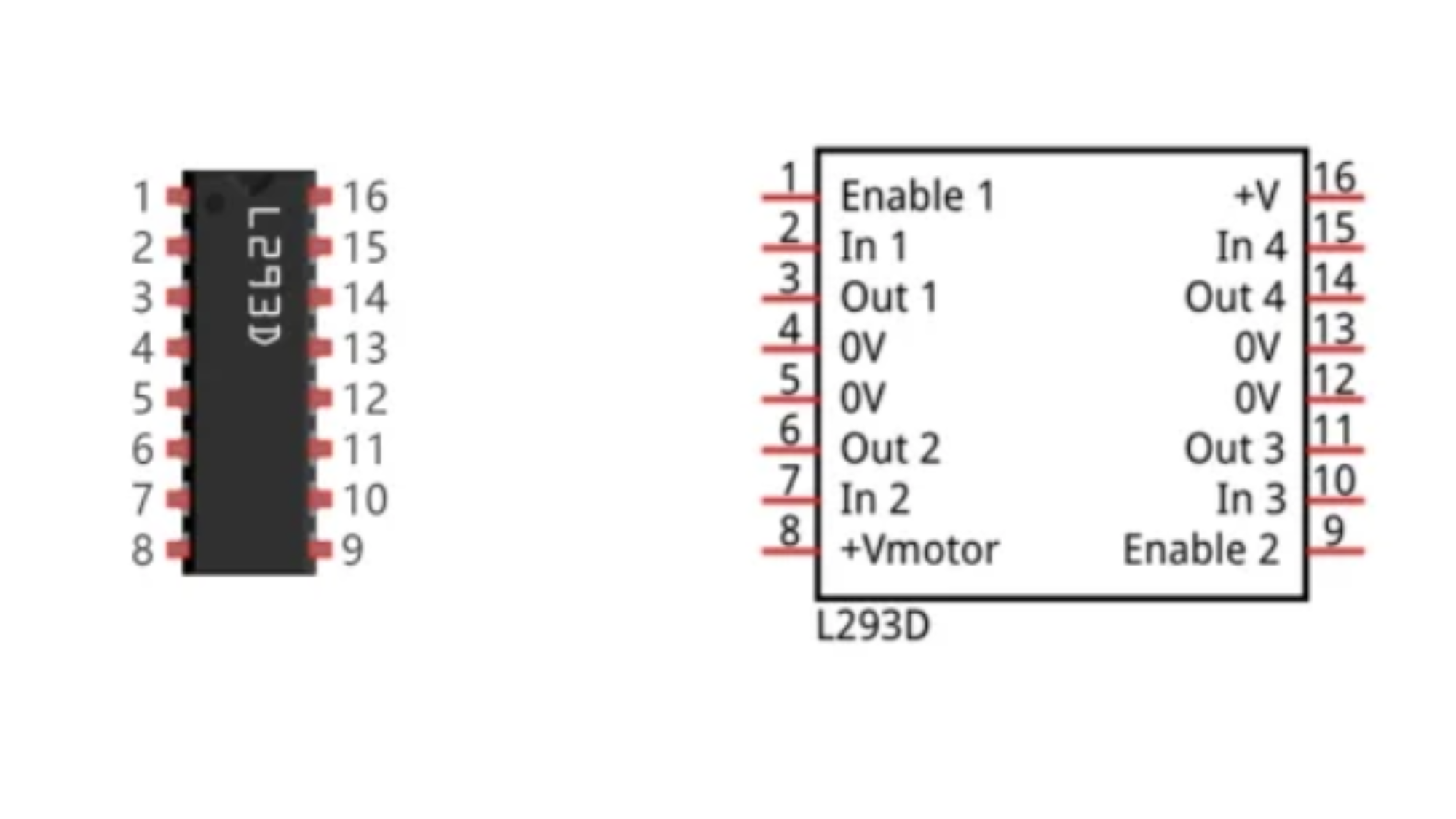
Port description of L293D module is as follows:
| Pin name | Pin number | Description |
| In x | 2, 7, 10, 15 | Channel x digital signal input pin |
| Out x | 3, 6, 11, 14 | Channel x output pin, input high or low level according to In x pin, get connected to +Vmotor or 0V |
| Enable1 | 1 | Channel 1 and channel 2 enable pin, high level enable |
| Enable2 | 9 | Channel 3 and channel 4 enable pin, high level enable |
| 0V | 4, 5, 12, 13 | Power cathode (GND) |
| +V | 16 | Positive electrode (VCC) of power supply, supply voltage 4.5~36V |
| +Vmotor | 8 | Positive electrode of load power supply, provide power supply for the Out pin x, the supply voltage is +V~36V |
When using L293D to drive DC motor, there are usually two kinds of connection.
The following connection option uses one channel of the L239D, which can control motor speed through
the PWM, However the motor then can only rotate in one direction.
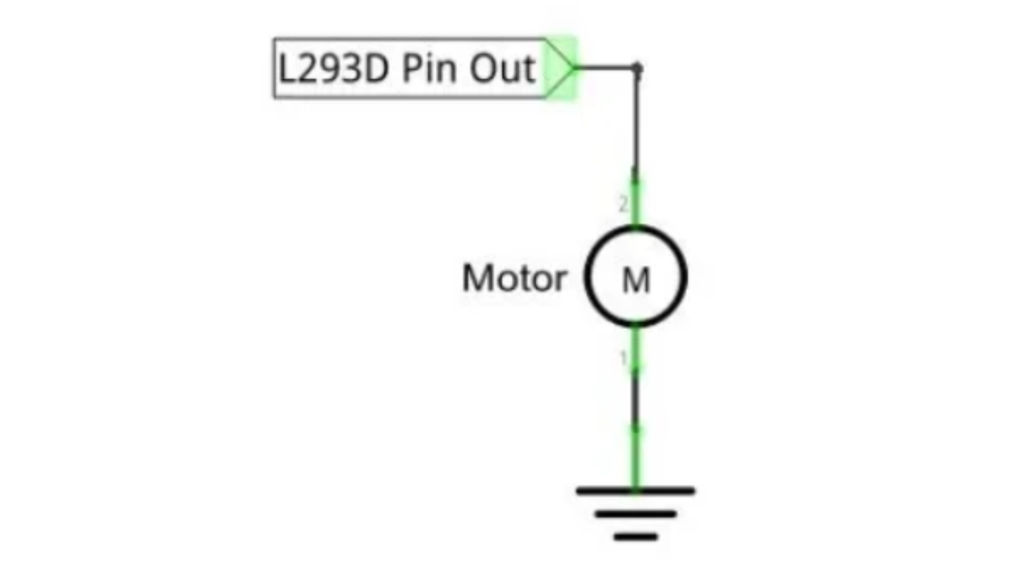
The following connection uses two channels of the L239D: one channel outputs the PWM wave, and the
other channel connects to GND. Therefore, you can control the speed of the motor. When these two
channel signals are exchanged, not only controls the speed of motor, but also can control the speed of the motor.
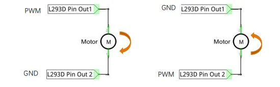
In practical use the motor is usually connected to channel 1 and by outputting different levels to in1 and in2
to control the rotational direction of the motor, and output to the PWM wave to Enable1 port to control the
motor’s rotational speed. If the motor is connected to channel 3 and 4 by outputting different levels to in3
and in4 to control the motor’s rotation direction, and output to the PWM wave to Enable2 pin to control the
motor’s rotational speed.
Circuit Diagram / Wiring
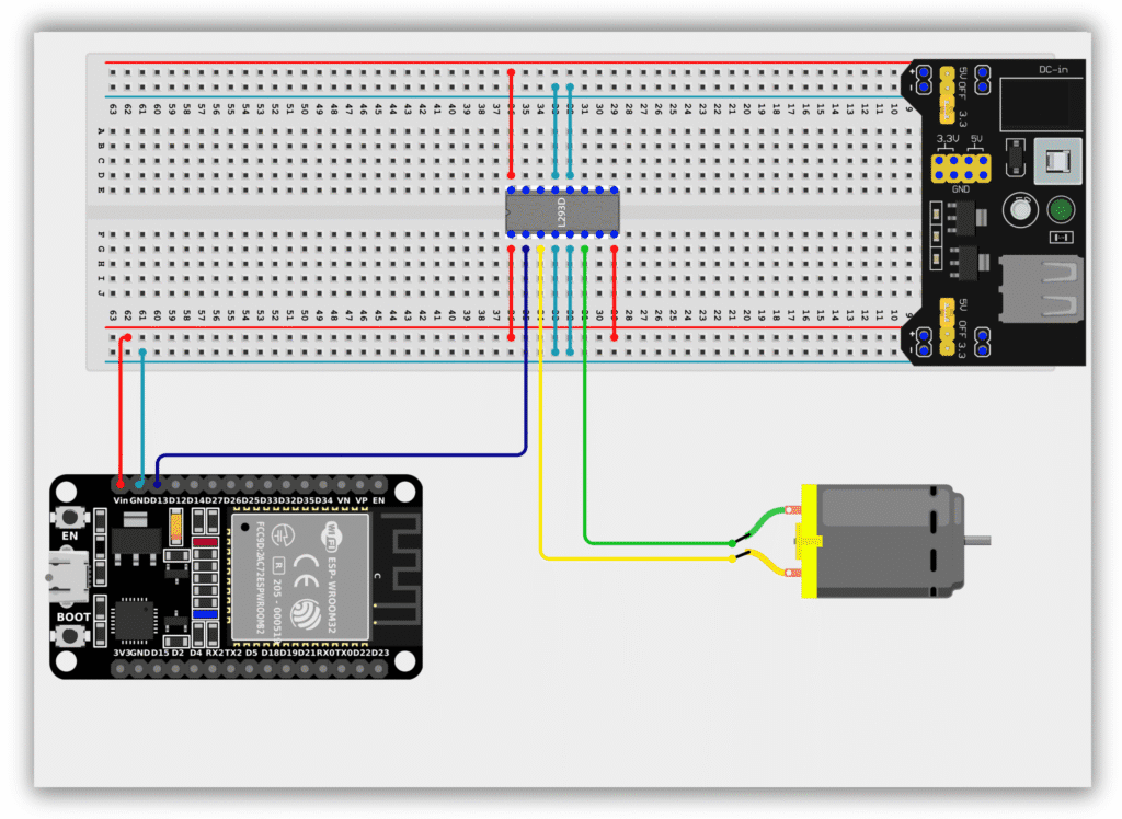
- ESP32 GPIO 13 → L293D IN1 (Pin 2)
- L293D OUT1 (Pin 3) → Motor Terminal 1
- L293D OUT2 (Pin 6) → Motor Terminal 2
- L293D EN1 (Pin 1) → 5V
- L293D VCC1 (Pin 16) → 3.3V (ESP32)
- L293D VCC2 (Pin 8) → Motor Supply (5V–12V)
- L293D GND (Pins 4, 5, 12, 13) → GND
- ESP32 GND → L293D GND
Code / Programming
/*
  Filename: ol_dc_motor.ino
  Description: Controls a DC motor using ESP32 and L293D
  Author: www.oceanlabz.in
  Modification: 1/4/2025
*/

#define MOTOR_PIN 13

void setup() {
  pinMode(MOTOR_PIN, OUTPUT);
}

void loop() {
  digitalWrite(MOTOR_PIN, HIGH);   // Motor ON
  delay(2000);

  digitalWrite(MOTOR_PIN, LOW);    // Motor OFF
  delay(2000);
}
Explanation
- The MOTOR_PIN is connected to the IN1 pin of the L293D motor driver.
- When GPIO 13 is set HIGH, the L293D drives the motor and it starts rotating.
- When GPIO 13 is set LOW, the motor stops.
- The motor continuously turns ON and OFF every two seconds.
Troubleshooting
- Ensure that the L293D IC is inserted correctly on the breadboard.
- Verify that the motor supply voltage is connected to VCC2 (Pin 8).
- Check that all GND pins of the L293D are connected properly.
- If the motor does not rotate, verify the wiring between the ESP32, L293D, and motor.
- If the ESP32 resets while the motor runs, use a separate power supply for the motor and connect all grounds together.