Index
Introduction
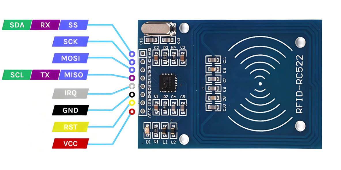
The MFRC522 is a widely used RFID module that communicates over SPI to read RFID tags.
It is commonly used for access control systems, attendance tracking, and automation projects.
The ESP32 can interface with the MFRC522 to read RFID tag data and process it for various applications.
In this tutorial, we’ll connect the MFRC522 RFID reader to the ESP32 and read RFID tag data.
Required Components
- ESP32 Board
- RFID Module with tags
- Jumper wires
- Breadboard
Pinout
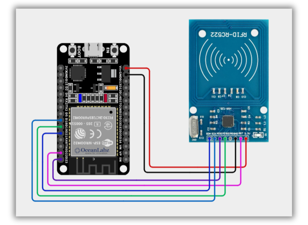
Circuit Diagram / Wiring
- RFID SENSOR VCC → VIN/5V (ESP32)
- RFID SENSOR GND → GND (ESP32)
- RFID SENSOR SDA → GPIO 21 (ESP32)
- RFID SENSOR SCK → GPIO 18 (ESP32)
- RFID SENSOR MOSI → GPIO 23 (ESP32)
- RFID SENSOR MISO → GPIO 19 (ESP32)
- RFID SENSOR RST → GPIO 22 (ESP32)
Code / Programming
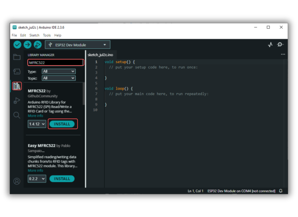
- Install Required Library (via Arduino Library Manager).
- Go to the “Libraries” tab on the left-hand side of the screen.
- Click on the “Library Manager” button (book icon) at the top of the Libraries tab.
- In the Library Manager window, type “MFRC522” in the search bar.
- Locate the “MFRC522” library click on the “Install” button next to it.
- Wait for the library to be installed, and you’re ready to use the MFRC522 library in your projects.
/*
Filename: ol_rfid_reader_uid.ino
Description: Reads RFID card using MFRC522 module and prints UID via Serial Monitor on ESP32
Author: www.oceanlabz.in
Modification: 1/4/2025
*/

#include <SPI.h>
#include <MFRC522.h>

// Define RFID module pins
#define RST_PIN 22   // Reset pin
#define SS_PIN 21    // SDA / Slave Select pin

MFRC522 mfrc522(SS_PIN, RST_PIN);  // Create MFRC522 instance

void setup() {
  Serial.begin(115200);       // Start Serial communication
  SPI.begin();                // Initialize SPI bus
  mfrc522.PCD_Init();         // Initialize RFID reader
  Serial.println("Place your RFID card near the reader.");
}

void loop() {
  // Check if a new card is present
  if (mfrc522.PICC_IsNewCardPresent() && mfrc522.PICC_ReadCardSerial()) {
    Serial.print("UID tag: ");
    for (byte i = 0; i < mfrc522.uid.size; i++) {
      Serial.print(mfrc522.uid.uidByte[i], HEX);
      Serial.print(" ");
    }
    Serial.println();
    mfrc522.PICC_HaltA();  // Stop reading current card
  }
}
Explanation
- The MFRC522 RFID reader is initialized and configured using the
mfrc522.PCD_Init()function. - When a card is detected, its UID (Unique Identifier) is read and printed to the Serial Monitor.
mfrc522.PICC_HaltA()stops communication with the card after reading the UID.
Troubleshooting
- Ensure the wiring connections between the MFRC522 and the ESP32 are correct, particularly the SPI pins.
- If the RFID card isn’t detected, try moving it closer or ensure that the card is compatible with the MFRC522.
- If the Serial Monitor shows no output, check for issues in power supply and ensure that the
SPIandMFRC522libraries are correctly installed.
Project 1: Smart Access Control System with RFID, Servo, and OLED Display
Introduction
This project is a Smart Access Control System using RFID technology powered by the ESP32 for secure and wireless authentication. When an authorized RFID tag is scanned, a servo motor unlocks, status LEDs indicate access approval or denial, and an OLED display shows real-time messages. The ESP32 also drives a buzzer for audible feedback, making the system responsive, secure, and ideal for IoT-based access management.
Required Components
- ESP32 Board
- MFRC522 RFID module, RFID tags
- Servo Motor
- OLED Display
- Buzzer Module
- 2x LEDs (Green,Red)
- Resistor 220 Ohm (2x)
- Jumper Wires
- Breadboard
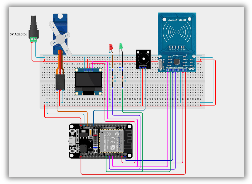
Circuit Diagram / Wiring
- RFID
- RFID SENSOR 3.3V → 3.3V (ESP32)
- RFID SENSOR GND → GND (ESP32)
- RFID SENSOR SDA → GPIO 21 (ESP32)
- RFID SENSOR SCK → GPIO 18 (ESP32)
- RFID SENSOR MOSI → GPIO 23 (ESP32)
- RFID SENSOR MISO → GPIO 19 (ESP32)
- RFID SENSOR RST → GPIO 22 (ESP32)
- Servo Motor
- Servo (RED) VCC → VIN/5V (ESP32) an external 5V power supply
- Servo (BROWN) GND → GND (ESP32)
- Servo (ORENG) PWM → GPIO 13 (ESP32)
- OLED Display
- OLED VCC → VIN/5V (ESP32)
- OLED GND → GND (ESP32)
- OLED SDA → GPIO 21 (ESP32)
- OLED SCK → GPIO 22 (ESP32)
- Buzzer Module
- Buzzer VCC → VIN/5V (ESP32)
- Buzzer GND → GND (ESP32)
- Buzzer SINGNAL → GPIO 14 (ESP32)
- LEDs
- Connect the red LED anode to GPIO 19 (via a 220-ohm resistor) and cathode to GND.
- Connect the green LED anode to GPIO 18 (via a 220-ohm resistor) and cathode to GND.
Code / Programming
- Install Required Libraries (via Arduino Library Manager).
- Go to the “Libraries” tab on the left-hand side of the screen.
- Click on the “Library Manager” button (book icon) at the top of the Libraries tab.
- In the Library Manager window, type “Adafruit_GFX” in the search bar.
- Locate the “Adafruit_GFX” library click on the “Install” button next to it.
- Wait for the library to be installed, and you’re ready to use the Adafruit_GFX library in your projects.
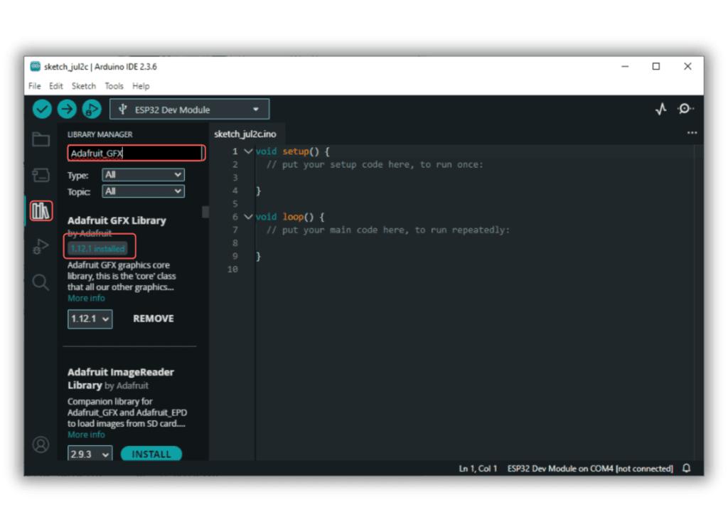
- Repeat the process to download all the libraries.
/*
Filename: ol_rfid_servo_access.ino
Description: RFID-based access system with OLED, LED indication, buzzer, and servo-controlled lock using ESP32
Author: www.oceanlabz.in
Modification: 1/4/2025
*/

#include <SPI.h>
#include <MFRC522.h>
#include <Adafruit_GFX.h>
#include <Adafruit_SSD1306.h>
#include <Servo.h>

// ESP32 Pin Definitions
#define RST_PIN         22   // RFID reset pin
#define SS_PIN          21   // RFID SDA (SS) pin
#define GREEN_LED       18   // Green LED for access granted
#define RED_LED         19   // Red LED for access denied
#define SERVO_PIN       13   // Servo control pin
#define BUZZER_PIN      14   // Buzzer pin
#define SCREEN_ADDRESS  0x3C // OLED I2C address

// OLED setup
#define SCREEN_WIDTH 128
#define SCREEN_HEIGHT 64
Adafruit_SSD1306 display(SCREEN_WIDTH, SCREEN_HEIGHT, &Wire);

// RFID reader
MFRC522 rfid(SS_PIN, RST_PIN);

// Servo motor
Servo myServo;

// Predefined authorized UID
byte authorizedUID[] = {0x83, 0x4D, 0x4C, 0xC5};

void setup() {
  Serial.begin(115200);
  SPI.begin();
  rfid.PCD_Init();

  Wire.begin();
  if (!display.begin(SSD1306_SWITCHCAPVCC, SCREEN_ADDRESS)) {
    Serial.println("SSD1306 OLED init failed");
    while (1);
  }

  display.clearDisplay();
  display.setTextSize(2);
  display.setTextColor(SSD1306_WHITE);

  pinMode(GREEN_LED, OUTPUT);
Steps to Use
Scan the New Card:
Upload the code to your ESP32. When you bring a new card close to the RFID reader, the UID of the card will be printed in the Serial Monitor.
- Open the Serial Monitor in the Arduino IDE (set baud rate to 115200).
- Note down the UID printed, e.g.,
UID: 83 4D 4C C5.
Update the Authorized UID in Code:
Replace the current authorizedUID array with the new card’s UID. For example:
byteauthorizedUID[] = {0x83, 0x4D, 0x4C, 0xC5}; // Replace with your new UID |
Re-upload the Code:
After replacing the UID, save the code and upload it back to the ESP32.
Test with the New Card:
Bring the new card close to the RFID reader to confirm that access is granted.
Example:
If the new card’s UID is A1 B2 C3 D4, update the code like this:
byteauthorizedUID[] = {0xA1, 0xB2, 0xC3, 0xD4}; |
Explanation
- If the card matches, it grants access by unlocking a servo (90°), lighting the green LED, and showing “Access Granted” on an OLED display.
- If the card doesn’t match, it denies access by beeping, lighting the red LED, and showing “Access Denied.”
- The card’s UID is printed to the Serial Monitor for debugging or finding new card UIDs.
- An OLED display is used to show system status messages like “Ready for Scan.”
- The system locks the servo again after 3 seconds and resets for the next scan.
Troubleshooting
- RFID Scanning Issues: Verify wiring and library setup; ensure tags are functional and authorized in the code.
- Servo Not Moving: Check power supply and connections; use an external source if needed for sufficient current.
- OLED Display Blank: Confirm I2C connections, correct I2C address in the code, and secure wiring.
- LEDs or Buzzer Not Working: Double-check pin assignments in the code and test components independently.
- System Unresponsive: Ensure all modules are powered properly and test each component separately to isolate issues.