Index

Introduction
In this tutorial, we are using a pulse sensor with Arduino to measure heart rate.
The sensor detects blood flow changes in the fingertip using infrared light.
Arduino reads the signal and processes it to determine real-time heartbeats.
It’s commonly used in DIY health monitors and wearable fitness projects.
Required Components
- Arduino UNO
- Pulse Sensor
- Jumper wires
- Breadboard
Pinout
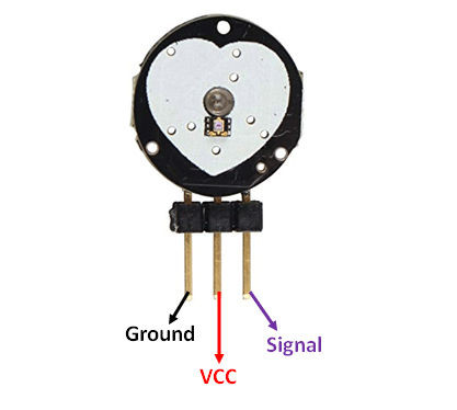
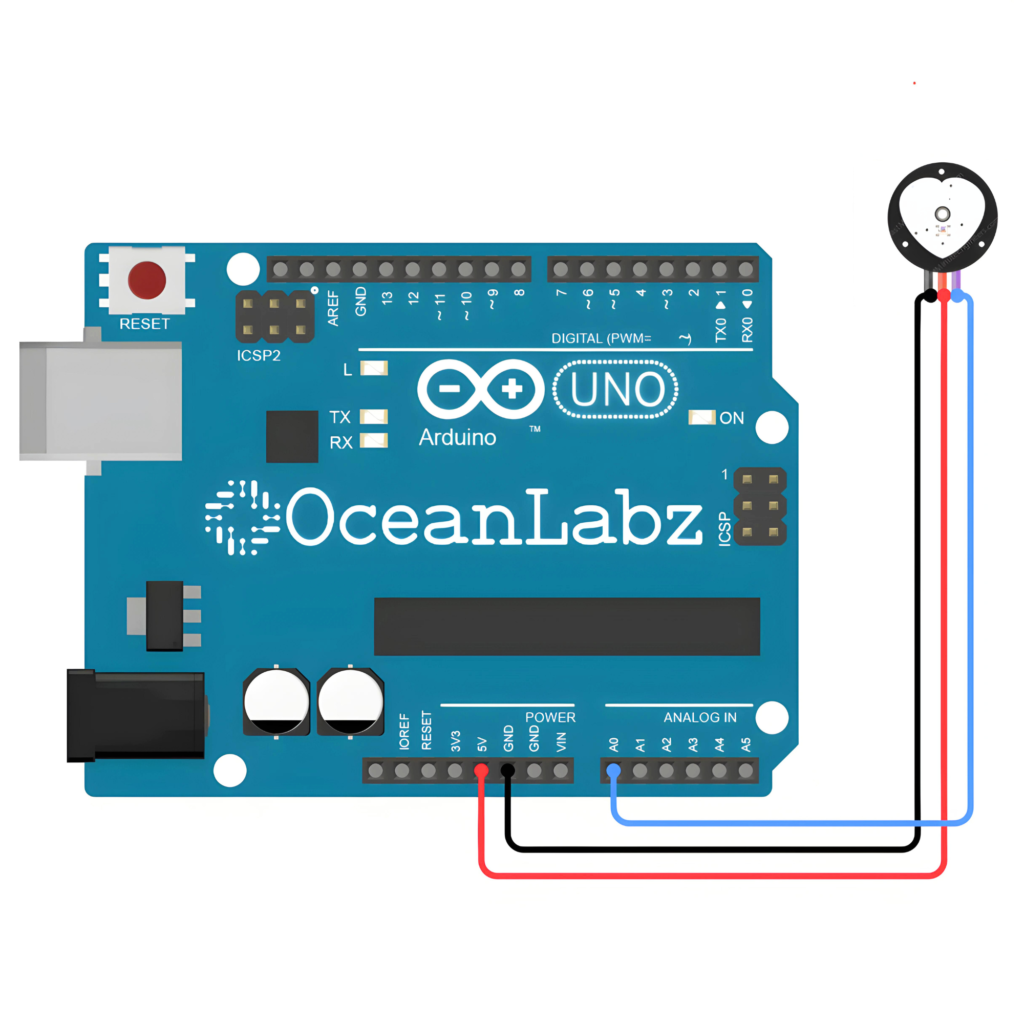
Circuit Diagram / Wiring
- Pulse Sensor VCC → 5V (Arduino)
- Pulse Sensor GND → GND (Arduino)
- Pulse Sensor Signal → A0 (Arduino)
Arduino Code / Programming
const int pulsePin = A0; // Pulse sensor connected to analog pin A0
int signal = 0;          // Variable to store pulse value

void setup() {
  Serial.begin(9600);    // Start Serial Monitor at 9600 baud
}

void loop() {
  signal = analogRead(pulsePin);   // Read the pulse sensor value
  Serial.println(signal);          // Print the value to the Serial Monitor
  delay(10);                       // Small delay for smooth reading
}
Explanation
- The pulse sensor uses an IR LED and photodetector to detect heartbeat pulses.
- Light absorption changes with each heartbeat, generating a signal.
- Arduino reads this signal to measure heart rate in BPM (beats per minute).
Troubleshooting
- Ensure the sensor is firmly placed on the fingertip for consistent readings.
- Avoid movement; motion can cause signal noise or false readings.
- Check power supply (3.3V/5V) and monitor raw signal in Serial Plotter if needed.