Index
Introduction
This project uses a rotary encoder with an ESP32 to detect rotational movement and control a counter based on the direction of rotation.
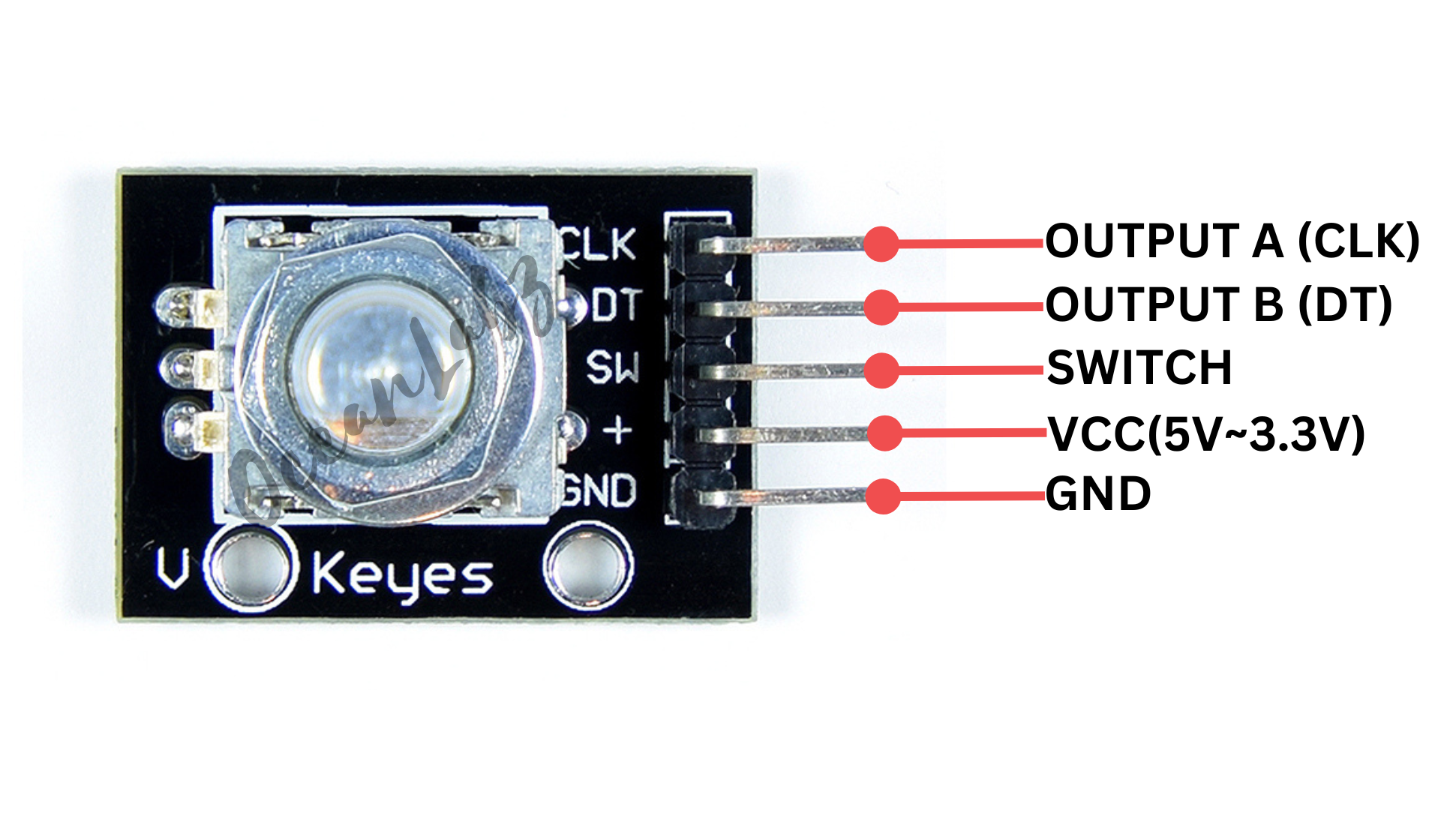
The encoder has three main pins: CLK (clock), DT (data), and SW (switch).
Rotating the encoder increases or decreases the position count, which is displayed on the Serial Monitor.
The switch pin can also be used to detect button presses, making it useful for interactive control applications with the ESP32.
Required Components
- ESP32 Board
- Rotary encoder (e.g., KY-040)
- Breadboard
- Jumper wires
Pinout
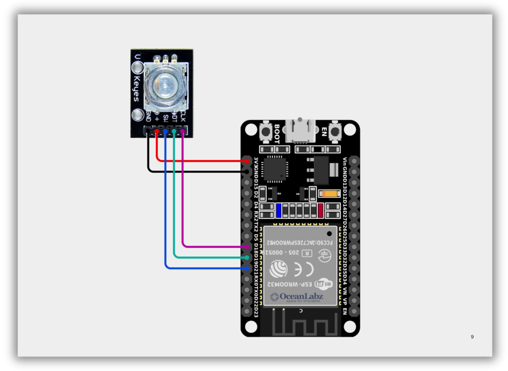
Circuit Diagram / Wiring
- ROTARY VCC → 5V (ESP32)
- ROTARY GND → GND (ESP32)
- ROTARY CLK → Pin 18 (ESP32)
- ROTARY DT → Pin 19 (ESP32)
- ROTARY SW → Pin 21 (ESP32)
Code / Programming
#define CLK 18   // GPIO18 connected to CLK
#define DT 19    // GPIO19 connected to DT
#define SW 21    // GPIO21 connected to SW (optional)

int counter = 0;  // Stores the position count
int currentStateCLK;
int lastStateCLK;

void setup() {
  pinMode(CLK, INPUT);
  pinMode(DT, INPUT);
  pinMode(SW, INPUT_PULLUP);  // Enable internal pull-up for the button

  lastStateCLK = digitalRead(CLK);  // Read initial CLK state

  Serial.begin(115200);  // Faster serial speed for ESP32
}

void loop() {
  currentStateCLK = digitalRead(CLK);

  // Detect rotation
  if (currentStateCLK != lastStateCLK) {
    if (digitalRead(DT) != currentStateCLK) {
      counter++;  // Clockwise
    } else {
      counter--;  // Counterclockwise
    }
    Serial.print("Position: ");
    Serial.println(counter);
  }

  lastStateCLK = currentStateCLK;

  // Detect button press
  if (digitalRead(SW) == LOW) {
    Serial.println("Button Pressed");
    delay(200);  // Simple debounce
  }
}
Explanation
- A rotary encoder outputs signals from CLK and DT pins to detect direction and steps of rotation.
- The ESP32 reads these signals to increment or decrement a counter, which is shown on the Serial Monitor.
- The optional SW pin detects button presses, useful for selections or resets in interactive projects.
Troubleshooting
- Ensure you’re using GPIOs that support digital input (avoid strapping/boot pins like GPIO0, GPIO2, GPIO15).
- If the counter skips or behaves erratically, add software debounce or use interrupt-based reading.
- For the button, use
INPUT_PULLUPand verify the SW pin is wired to GND through the encoder when pressed.
Project 1: ESP32 Web-Controlled LED Dimmer with Rotary Encoder
Introduction
This project uses an ESP32, rotary encoder, and PWM to control the brightness of an LED.
As the encoder is rotated, the brightness increases or decreases in real-time.
The ESP32 hosts a web interface displaying live brightness updates with a glowing bulb animation.
It combines hardware interaction with AJAX-powered web visuals for a responsive lighting control demo.
#include <WiFi.h>
#include <WebServer.h>

// Wi-Fi credentials
const char* ssid = "YOUR_SSID";
const char* password = "YOUR_PASSWORD";

// Rotary Encoder Pins
#define ENCODER_CLK 18
#define ENCODER_DT  19

// LED pin (onboard LED is GPIO 2)
#define LED_PIN 2
#define PWM_CHANNEL 0
#define PWM_FREQ 5000
#define PWM_RES 8  // 8-bit: 0–255

int brightness = 128;  // initial brightness
int lastClkState;

// Web server
WebServer server(80);

int clampBrightness(int val) {
  return constrain(val, 0, 255);
}

// Serve HTML with AJAX
void handleRoot() {
  String html = "<!DOCTYPE html><html><head><meta charset='utf-8'>";
  html += "<title>ESP32 LED Brightness</title>";
  html += "<style>";
  html += "body{font-family:sans-serif;text-align:center;background:#111;color:#eee;}";
  html += "svg{margin-top:20px;width:150px;height:150px;filter:drop-shadow(0 0 10px rgba(255,255,100,0.3));}";
  html += "input[type=range]{width:50%;}";
  html += "</style></head><body>";
  html += "<h2>Rotary-Controlled Light Bulb</h2>";
  html += "<p>Brightness: <b id='brightnessVal'>" + String(brightness) + "</b> / 255</p>";
  html += "<input type='range' min='0' max='255' value='" + String(brightness) + "' id='brightnessSlider' disabled><br>";

  html += "<svg viewBox='0 0 64 64'>";
  html += "<path id='bulb' d='M32,2C20.3,2,11,11.3,11,23c0,6.6,3.2,12.4,8.2,16.2c1.5,1.1,2.8,3.1,2.8,5.2V49h20v-4.6c0-2.1,1.3-4.1,2.8-5.2 C49.8,35.4,53,29.6,53,23C53,11.3,43.7,2,32,2z' fill='rgba(255, 255, 100," + String((float)brightness / 255.0, 3) + ")'/>";
  html += "<rect x='26' y='49' width='12' height='3' fill='#aaa'/>";
  html += "<rect x='24' y='52' width='16' height='4' fill='#888'/>";
  html += "</svg>";

  html += "<script>";
  html += "function updateBrightness() {";
  html += "fetch('/brightness').then(response => response.text()).then(data => {";
  html += "let brightness = parseInt(data);";
  html += "document.getElementById('brightnessVal').innerText = brightness;";
  html += "document.getElementById('brightnessSlider').value = brightness;";
  html += "let opacity = brightness / 255.0;";
  html += "document.getElementById('bulb').setAttribute('fill', 'rgba(255, 255, 100,' + opacity.toFixed(3) + ')');";
  html += "});";
  html += "}";
  html += "setInterval(updateBrightness, 300);";
  html += "</script>";

  html += "</body></html>";

  server.send(200, "text/html", html);
}

// API endpoint to return current brightness
void handleBrightness() {
  server.send(200, "text/plain", String(brightness));
}

void setup() {
  Serial.begin(115200);

  pinMode(ENCODER_CLK, INPUT);
  pinMode(ENCODER_DT, INPUT);
  lastClkState = digitalRead(ENCODER_CLK);

  // Setup PWM for onboard LED
  ledcAttachChannel(LED_PIN, PWM_FREQ, PWM_RES, PWM_CHANNEL );
  ledcWrite(PWM_CHANNEL, brightness);

  // Connect Wi-Fi
  WiFi.begin(ssid, password);
  Serial.print("Connecting to WiFi");
  while (WiFi.status() != WL_CONNECTED) {
    delay(500);
    Serial.print(".");
  }
  Serial.println("\nConnected! IP: " + WiFi.localIP().toString());

  server.on("/", handleRoot);
  server.on("/brightness", handleBrightness);
  server.begin();
}

void loop() {
  server.handleClient();

  int clkNow = digitalRead(ENCODER_CLK);
  if (clkNow != lastClkState) {
    if (digitalRead(ENCODER_DT) != clkNow) {
      brightness += 5;
      Serial.println("Clockwise → Brightness: " + String(brightness));
    } else {
      brightness -= 5;
      Serial.println("Counter-Clockwise ← Brightness: " + String(brightness));
    }

    brightness = clampBrightness(brightness);
    ledcWrite(PWM_CHANNEL, brightness);
    delay(2);  // basic debounce
  }

  lastClkState = clkNow;
}
Explanation
- A rotary encoder adjusts the LED brightness by changing the PWM signal on the ESP32.
- The ESP32 hosts a web page showing real-time brightness with a glowing bulb animation.
- An AJAX script fetches brightness updates every 300ms for smooth UI feedback.
Troubleshooting
- LED not responding? Check
LED_PINand make sureledcAttachChannel()is set correctly. - No encoder response? Ensure correct wiring and confirm you’re using valid GPIOs (like 18 & 19).
- No webpage? Verify your Wi-Fi connection and access the ESP32’s local IP from your browser.