Index
Introduction
This project uses a rotary encoder with an ESP32 to detect rotational movement and control a counter based on the direction of rotation.
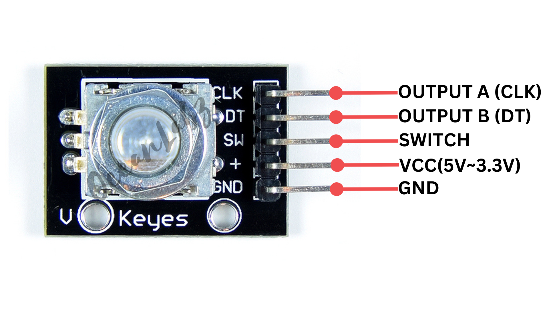
The encoder has three main pins: CLK (clock), DT (data), and SW (switch).
Rotating the encoder increases or decreases the position count, which is displayed on the Serial Monitor.
The switch pin can also be used to detect button presses, making it useful for interactive control applications with the ESP32.
Required Components
- ESP32 Board
- Rotary encoder (e.g., KY-040)
- Breadboard
- Jumper wires
Pinout
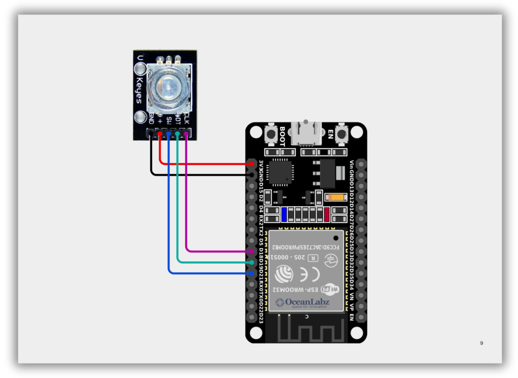
Circuit Diagram / Wiring
- ROTARY VCC → 5V (ESP32)
- ROTARY GND → GND (ESP32)
- ROTARY CLK → Pin 18 (ESP32)
- ROTARY DT → Pin 19 (ESP32)
- ROTARY SW → Pin 21 (ESP32)
Code / Programming
#define CLK 18   // GPIO18 connected to CLK
#define DT 19    // GPIO19 connected to DT
#define SW 21    // GPIO21 connected to SW (optional)

int counter = 0;  // Stores the position count
int currentStateCLK;
int lastStateCLK;

void setup() {
  pinMode(CLK, INPUT);
  pinMode(DT, INPUT);
  pinMode(SW, INPUT_PULLUP);  // Enable internal pull-up for the button

  lastStateCLK = digitalRead(CLK);  // Read initial CLK state

  Serial.begin(115200);  // Faster serial speed for ESP32
}

void loop() {
  currentStateCLK = digitalRead(CLK);

  // Detect rotation
  if (currentStateCLK != lastStateCLK) {
    if (digitalRead(DT) != currentStateCLK) {
      counter++;  // Clockwise
    } else {
      counter--;  // Counterclockwise
    }
    Serial.print("Position: ");
    Serial.println(counter);
  }

  lastStateCLK = currentStateCLK;

  // Detect button press
  if (digitalRead(SW) == LOW) {
    Serial.println("Button Pressed");
    delay(200);  // Simple debounce
  }
}
Explanation
- A rotary encoder outputs signals from CLK and DT pins to detect direction and steps of rotation.
- The ESP32 reads these signals to increment or decrement a counter, which is shown on the Serial Monitor.
- The optional SW pin detects button presses, useful for selections or resets in interactive projects.
Troubleshooting
- Ensure you’re using GPIOs that support digital input (avoid strapping/boot pins like GPIO0, GPIO2, GPIO15).
- If the counter skips or behaves erratically, add software debounce or use interrupt-based reading.
- For the button, use
INPUT_PULLUPand verify the SW pin is wired to GND through the encoder when pressed.