Index
Introduction
Servo motors are precise actuators that rotate to a specific angle between 0° and 180°.
Using the ESP32’s PWM (Pulse Width Modulation) capabilities, you can control servo position easily.
This is useful for robotics, camera gimbals, and automation systems.
Required Components
- ESP32 Board
- Servo Motor
- Jumper wires
- Breadboard
- 5V Power Supply, Battery
Pinout

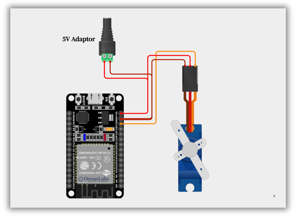
Circuit Diagram / Wiring
- SERVO (5V) → ESP32 VIN an external 5V power supply
- SERVO (GND) → ESP32 GND
- SERVO (Signal) → ESP32 GPIO 13
Code / Programming
- Install Required Library (via Arduino Library Manager).
- Go to the “Libraries” tab on the left-hand side of the screen.
- Click on the “Library Manager” button (book icon) at the top of the Libraries tab.
- In the Library Manager window, type “ESP32Servo” in the search bar.
- Locate the “ESP32Servo” library click on the “Install” button next to it.
- Wait for the library to be installed, and you’re ready to use the ESP32Servo library in your projects.

/*
Filename: ol_servo_sweep_esp32servo.ino
Description: ESP32 servo control using ESP32Servo library
*/
#include <ESP32Servo.h>

Servo myServo;

void setup() {
  // Allow allocation of all timers
  ESP32PWM::allocateTimer(0);
  ESP32PWM::allocateTimer(1);
  ESP32PWM::allocateTimer(2);
  ESP32PWM::allocateTimer(3);

  myServo.setPeriodHertz(50);    // Standard 50Hz servo
  myServo.attach(13, 500, 2400); // Attach servo to pin 13, min/max pulse width in microseconds
}

void loop() {
  myServo.write(0);
  delay(1000);
  myServo.write(90);
  delay(1000);
  myServo.write(180);
  delay(1000);
}
Explanation
- Optimized for ESP32: Uses the ESP32Servo library specifically designed for better PWM control on ESP32 chips
- Precise PWM Configuration: Sets 50Hz servo frequency and custom pulse widths (500-2400μs) for accurate positioning
- Simple Sweep Control: Moves servo between 0°, 90°, and 180° positions with 1-second delays between movements
Testing & Troubleshooting
- Servo Not Moving? Check wiring (power, ground, signal) and ensure power supply provides enough current (5V/1A+)
- Jittery Movement? Add a capacitor (100-1000μF) across servo power pins or use a separate power source
- Incorrect Positions? Calibrate pulse widths in
myServo.attach()(adjust 500,2400 values) for your specific servo model
Project 1: Creating Ultrasonic Radar Scanner with Servo Control
Introduction
Smart Radar System Using Sonar and ESP32 is a real-time object detection project that combines an ultrasonic sensor, servo motor, and ESP32. It scans the surroundings, measures distances, and sends the data to a radar-style interface created using Processing. Ideal for IoT, robotics, and automation, it enables accurate detection and environmental mapping. Perfect for learning sensor control, wireless data handling, and visualization with the ESP32.
Required Components
- ESP32 Board
- SG90 servo motor
- Ultrasonic Sensor
- Jumper wires
- Breadboard (optional)
- Computer: With Processing IDE software installed.
Circuit Diagram / Wiring
- Ultrasonic Sensor with ESP32
- ULTRASONIC SENSOR VCC → 5V (ESP32)
- ULTRASONIC SENSOR GND → GND (ESP32)
- ULTRASONIC SENSOR TRIG → GPIO 5 (ESP32)
- ULTRASONIC SENSOR ECHO → GPIO 18 (ESP32)
- Servo motor with ESP32
- SERVO MOTOR VCC → VIN (ESP32) an external 5V power supply
- SERVO MOTOR GND → GND (ESP32)
- SERVO MOTOR PWM → GPIO 13 (ESP32)

Code / Programming
/*
Filename: ol_servo_ultrasonic_scan.ino
Description: ESP32 code to scan area using servo and ultrasonic sensor, printing angle and distance.
Author: www.oceanlabz.in
Modification: 1/4/2025
*/
#include <ESP32Servo.h>    // Better ESP32 servo control
#include <NewPing.h>       // More reliable ultrasonic readings

// Ultrasonic Sensor Pins
#define TRIG_PIN  5
#define ECHO_PIN  18
#define MAX_DISTANCE 200   // Max distance in cm (adjust as needed)

Servo myServo;             // Create Servo object
NewPing sonar(TRIG_PIN, ECHO_PIN, MAX_DISTANCE); // Ultrasonic sensor

void setup() {
  Serial.begin(115200);

  // Initialize servo with custom pulse widths (adjust for your servo)
  myServo.attach(13, 500, 2400);  // Pin, min μs, max μs

  Serial.println("ESP32-S3 Servo + Ultrasonic Radar");
}

void loop() {
  // Sweep from 15° to 165°
  for (int angle = 15; angle <= 165; angle++) {
    updateRadar(angle);
  }

  // Sweep back from 165° to 15°
  for (int angle = 165; angle > 15; angle--) {
    updateRadar(angle);
  }
}

void updateRadar(int angle) {
  myServo.write(angle);
  delay(30);  // Give servo time to move

  // Get distance (median of 3 pings for reliability)
  unsigned int distance = sonar.ping_median(3) / US_ROUNDTRIP_CM;

  // Print angle and distance (CSV format)
  Serial.print(angle);
  Serial.print(",");
  Serial.print(distance);
  Serial.println();
}
Setup Processing Code
Install Processing Software:
Download and install Processing IDE.
Write or Paste Code:
Open Processing IDE and paste the radar visualization code provided.
- Adjust the
COM portin the Processing code to match your ESP32 port. - Set the
baud ratein Processing to the same value used in the Arduino IDE code (115200).
Run the Processing Code:
Click the Run button in Processing to start the radar visualization.
import processing.serial.*; // imports library for serial communication
import java.awt.event.KeyEvent; // imports library for reading the data from the serial port
import java.io.IOException;
Serial myPort; // defines Object Serial
// defubes variables
String angle="";
String distance="";
String data="";
String noObject;
float pixsDistance;
int iAngle, iDistance;
int index1=0;
int index2=0;
PFont orcFont;
void setup() {

 size (1200, 700); // ***CHANGE THIS TO YOUR SCREEN RESOLUTION***
 smooth();
 myPort = new Serial(this,"COMX", 115200);  // Replace COMX with your ESP32's port (e.g., "COM5")
 myPort.bufferUntil('.'); // reads the data from the serial port up to the character '.'. So actually it reads this: angle,distance.
}
void draw() {

  fill(98,245,31);
  // simulating motion blur and slow fade of the moving line
  noStroke();
  fill(0,4);
  rect(0, 0, width, height-height*0.065);

  fill(98,245,31); // green color
  // calls the functions for drawing the radar
  drawRadar();
  drawLine();
  drawObject();
  drawText();
}
void serialEvent (Serial myPort) { // starts reading data from the Serial Port
  // reads the data from the Serial Port up to the character '.' and puts it into the String variable "data".
  data = myPort.readStringUntil('.');
  data = data.substring(0,data.length()-1);

  index1 = data.indexOf(","); // find the character ',' and puts it into the variable "index1"
  angle= data.substring(0, index1); // read the data from position "0" to position of the variable index1 or thats the value of the angle the Arduino Board sent into the Serial Port
  distance= data.substring(index1+1, data.length()); // read the data from position "index1" to the end of the data pr thats the value of the distance

  // converts the String variables into Integer
  iAngle = int(angle);
  iDistance = int(distance);
}
void drawRadar() {
  pushMatrix();
  translate(width/2,height-height*0.074); // moves the starting coordinats to new location
  noFill();
  strokeWeight(2);
  stroke(98,245,31);
  // draws the arc lines
  arc(0,0,(width-width*0.0625),(width-width*0.0625),PI,TWO_PI);
  arc(0,0,(width-width*0.27),(width-width*0.27),PI,TWO_PI);
  arc(0,0,(width-width*0.479),(width-width*0.479),PI,TWO_PI);
  arc(0,0,(width-width*0.687),(width-width*0.687),PI,TWO_PI);
  // draws the angle lines
  line(-width/2,0,width/2,0);
  line(0,0,(-width/2)*cos(radians(30)),(-width/2)*sin(radians(30)));
  line(0,0,(-width/2)*cos(radians(60)),(-width/2)*sin(radians(60)));
  line(0,0,(-width/2)*cos(radians(90)),(-width/2)*sin(radians(90)));
  line(0,0,(-width/2)*cos(radians(120)),(-width/2)*sin(radians(120)));
  line(0,0,(-width/2)*cos(radians(150)),(-width/2)*sin(radians(150)));
  line((-width/2)*cos(radians(30)),0,width/2,0);
  popMatrix();
}
void drawObject() {
  pushMatrix();
  translate(width/2,height-height*0.074); // moves the starting coordinats to new location
  strokeWeight(9);
  stroke(255,10,10); // red color
  pixsDistance = iDistance*((height-height*0.1666)*0.025); // covers the distance from the sensor from cm to pixels
  // limiting the range to 40 cms
  if(iDistance<40){
    // draws the object according to the angle and the distance
  line(pixsDistance*cos(radians(iAngle)),-pixsDistance*sin(radians(iAngle)),(width-width*0.505)*cos(radians(iAngle)),-(width-width*0.505)*sin(radians(iAngle)));
  }
  popMatrix();
}
void drawLine() {
  pushMatrix();
  strokeWeight(9);
  stroke(30,250,60);
  translate(width/2,height-height*0.074); // moves the starting coordinats to new location
  line(0,0,(height-height*0.12)*cos(radians(iAngle)),-(height-height*0.12)*sin(radians(iAngle))); // draws the line according to the angle
  popMatrix();
}
void drawText() { // draws the texts on the screen

  pushMatrix();
  if(iDistance>40) {
  noObject = "Out of Range";
  }
  else {
  noObject = "In Range";
  }
  fill(0,0,0);
  noStroke();
  rect(0, height-height*0.0648, width, height);
  fill(98,245,31);
  textSize(25);

  text("10cm",width-width*0.3854,height-height*0.0833);
  text("20cm",width-width*0.281,height-height*0.0833);
  text("30cm",width-width*0.177,height-height*0.0833);
  text("40cm",width-width*0.0729,height-height*0.0833);
  textSize(40);
  text("OceanLabz", width-width*0.875, height-height*0.0277);
  text("Angle: " + iAngle +" °", width-width*0.48, height-height*0.0277);
  text("Distance: ", width-width*0.26, height-height*0.0277);
  if(iDistance<40) {
  text("        " + iDistance +" cm", width-width*0.225, height-height*0.0277);
  }
  textSize(25);
  fill(98,245,60);
  translate((width-width*0.4994)+width/2*cos(radians(30)),(height-height*0.0907)-width/2*sin(radians(30)));
  rotate(-radians(-60));
  text("30°",0,0);
  resetMatrix();
  translate((width-width*0.503)+width/2*cos(radians(60)),(height-height*0.0888)-width/2*sin(radians(60)));
  rotate(-radians(-30));
  text("60°",0,0);
  resetMatrix();
  translate((width-width*0.507)+width/2*cos(radians(90)),(height-height*0.0833)-width/2*sin(radians(90)));
  rotate(radians(0));
  text("90°",0,0);
  resetMatrix();
  translate(width-width*0.513+width/2*cos(radians(120)),(height-height*0.07129)-width/2*sin(radians(120)));
  rotate(radians(-30));
  text("120°",0,0);
  resetMatrix();
  translate((width-width*0.5104)+width/2*cos(radians(150)),(height-height*0.0574)-width/2*sin(radians(150)));
  rotate(radians(-60));
  text("150°",0,0);
  popMatrix();
}
Explanation
- Servo Motor Control: The servo motor rotates between 15° and 165° to scan the environment.
- Distance Measurement: The ultrasonic sensor sends a pulse, and the time taken for the echo to return is used to calculate distance.
- Data Output: The degree and corresponding distance values are printed to the Serial Monitor for each position of the servo motor.
- Looping Process: The servo sweeps back and forth, continuously measuring distance at each angle and sending the data for processing.