Index
Introduction
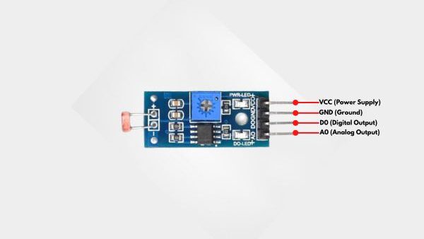
LDR sensor module is used to detect light intensity. It uses a light dependent resistor along with a comparator circuit, which provides both analog and digital output. The working of the LDR sensor module is simple. When light falls on the LDR, its resistance changes. The analog pin gives a continuous value based on light intensity. The digital pin compares this value with a preset level set by the potentiometer and gives a HIGH or LOW output.
Required Components
- ESP32 Board
- LDR Sensor
- LED
- 220Ω Resistor
- Breadboard
- Jumper Wires
Pinout
- DHT11 Sensor
- VCC: Power supply pin (3.3V to 5V)
- GND: Ground pin
- DO: Digital data output pin
- LED
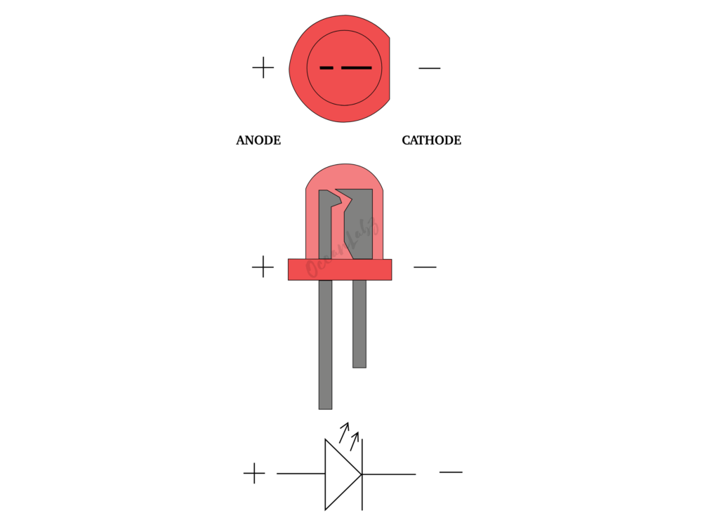
- LED Anode (+)
- LED Cathode (-)
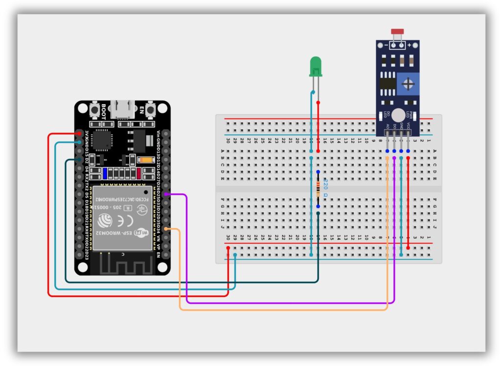
Circuit Diagram
- LDR Sensor
- LDR Sensor VCC → ESP32 3.3V
- LDR Sensor GND → ESP32 GND
- LDR Sensor D0 → ESP32 GPIO 25
- LDR Sensor A0 → ESP32 GPIO 34
- LED
- Anode (Long Leg) → ESP32 GPIO 2 (via 220Ω Resistor)
- Cathode (Short Leg) → GND
Code / Programming
#define LDR_ANALOG 34
#define LDR_DIGITAL 25
#define LED 2

void setup() {
  Serial.begin(115200);

  pinMode(LDR_DIGITAL, INPUT);
  pinMode(LED, OUTPUT);
}

void loop() {
  int analogValue = analogRead(LDR_ANALOG);
  int digitalValue = digitalRead(LDR_DIGITAL);

  Serial.print("Analog Value: ");
  Serial.print(analogValue);

  Serial.print(" | Digital Value: ");
  Serial.println(digitalValue);

  // LED control using digital output
  if (digitalValue == LOW) {
    digitalWrite(LED, HIGH); // Light detected
  } else {
    digitalWrite(LED, LOW);  // Dark
  }

  delay(500);
}
Explanation
- The ESP32 reads the LDR sensor using both analog pin (GPIO 34) and digital pin (GPIO 25), where analog gives the light intensity value and digital gives HIGH or LOW output.
- The analog value is shown on the Serial Monitor, while the digital output helps detect whether light is present or not based on the potentiometer setting on the sensor module.
- If light is detected (digital output LOW), the LED connected to GPIO 2 turns ON; otherwise, in darkness, the LED turns OFF.
Troubleshooting
- If the Serial Monitor shows no values, check the ESP32 board selection, correct COM port, and make sure the baud rate is set to 115200.
- If the LED does not turn ON or OFF, verify the LED polarity, wiring connections, and confirm it is connected to GPIO 2 correctly.
- If the LDR sensor is not detecting light changes, adjust the potentiometer on the sensor module and recheck the VCC, GND, AO, and DO pin connections.
Project 1: ESP32 Laser Security Beam
Introduction
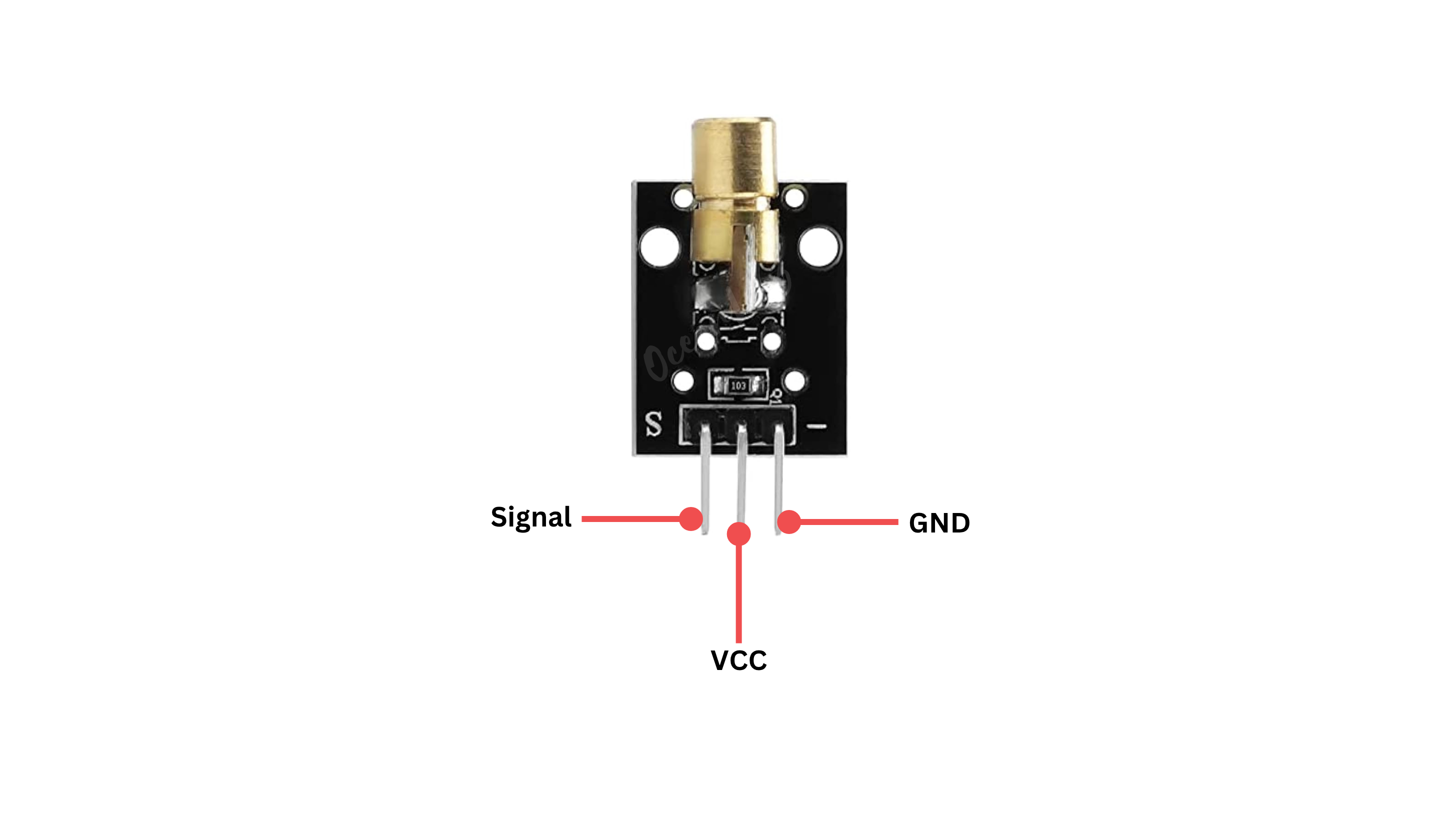
The KY-008 laser module emits a focused red laser beam, while the LDR (Light Dependent Resistor) detects changes in light intensity.
When the laser directly hits the LDR, its resistance remains low — but if the beam is interrupted, resistance increases.
With ESP32, this setup can be used for security triggers, object detection, or counting systems.
Required Components
- ESP32 Board
- Laser Module
- LDR Sensor Module
- Jumper wires
- Breadboard
Pinout
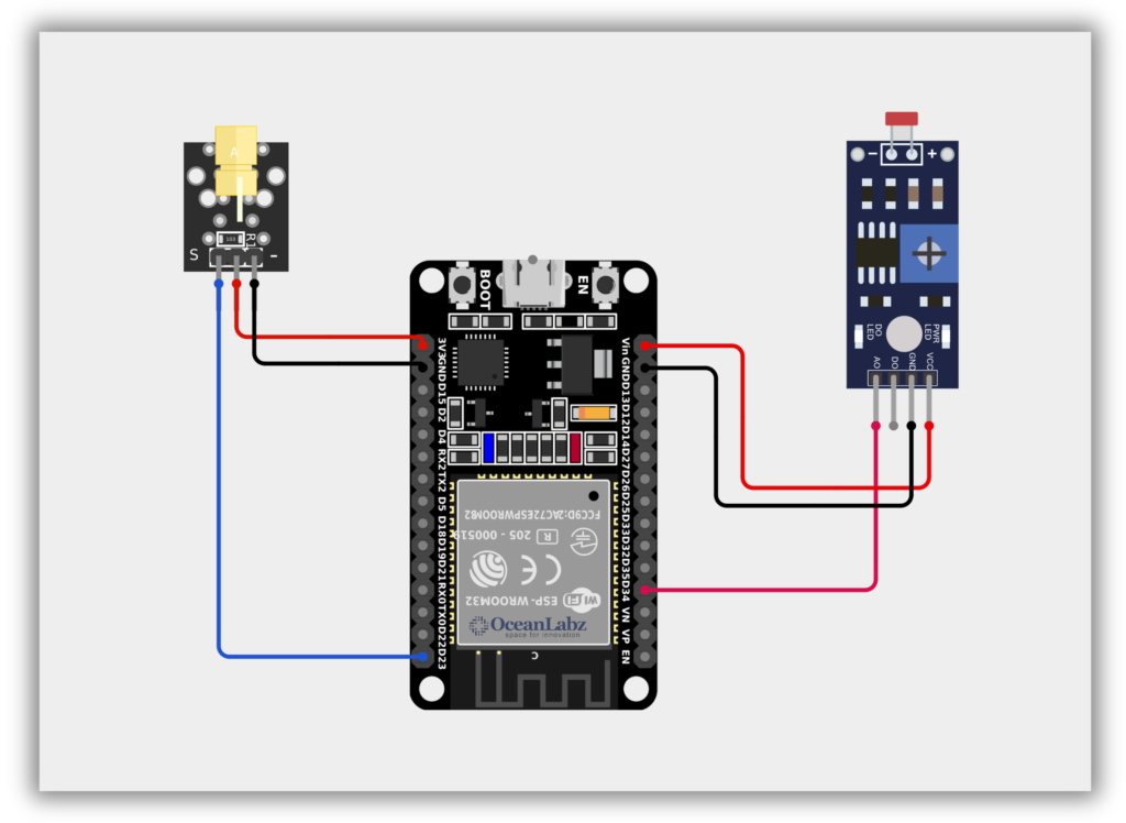
Circuit Diagram / Wiring
- Laser Module with ESP32
- Laser VCC → 3.3, 5V (ESP32)
- Laser GND → GND (ESP32)
- Laser Signal → 23 (ESP32)
- LDR Module with ESP32
- LDR VCC → 5V (ESP32)
- LDR GND → GND (ESP32)
- LDR A0 → 34 (ESP32)
Code / Programming
/*
Filename: ol_laser_tripwire.ino
Description: Detects interruption in laser beam using KY-008 and LDR sensor
Author: www.oceanlabz.in
Modification: 1/4/2025
*/

int laserPin = 23;      // Laser KY-008 connected to GPIO 23
int ldrPin = 34;        // LDR connected to ADC-capable GPIO 34

void setup() {
  pinMode(laserPin, OUTPUT);     // Set laser pin as output
  Serial.begin(115200);          // Start serial communication
}

void loop() {
  digitalWrite(laserPin, HIGH);           // Turn on the laser
  int ldrValue = analogRead(ldrPin);      // Read the LDR value

  Serial.print("LDR Value: ");
  Serial.println(ldrValue);

  // Check if laser beam is interrupted (LDR reads lower value)
  if (ldrValue < 500) {
    Serial.println("Laser beam interrupted!");
  }

  delay(200);  // Wait for 200ms before the next reading
}
Explanation
- The KY-008 laser module emits a beam, which directly hits the LDR sensor under normal conditions.
- The ESP32 reads the LDR’s analog value via an ADC pin to detect light intensity.
- If the beam is interrupted (e.g., by a hand or object), the LDR value drops, triggering an alert.
Troubleshooting
- Make sure the LDR is connected to an ADC-compatible pin like GPIO34–39 (not digital-only pins).
- If values don’t change, check laser alignment, LDR sensitivity, and adjust the threshold (e.g.,
ldrValue < 500). - If laser doesn’t light up, ensure it’s connected to a working digital pin and receiving proper voltage (3.3V or 5V).