Index

Introduction
The ESP32-S3-Zero are ultra-compact boards with castellated holes, designed for seamless integration into other host circuits. The ESP32-S3-Zero is equipped with a Type-C USB connector, providing access to most of the unutilized pins while maintaining a small footprint. It features the ESP32-FH4R2 SoC, which supports low-power Wi-Fi and Bluetooth 5.0, along with 4MB Flash and 2MB PSRAM. The module is also integrated with hardware-based encryption accelerators, RNG, HMAC, and Digital Signature modules, catering to the security requirements of IoT applications. With its low-power mode, the board is ideal for use in a variety of scenarios, including IoT devices, mobile gadgets, wearable technology, and smart home solutions.
Specifications
| Specification | Details |
|---|---|
| Processor | Xtensa® 32-bit LX7 dual-core, up to 240MHz |
| Wi-Fi & Bluetooth | 2.4GHz Wi-Fi (802.11 b/g/n), Bluetooth® 5 (LE) |
| Memory | 512KB SRAM, 384KB ROM, 4MB Flash, 2MB PSRAM |
| Module Features | Castellated module with onboard ceramic antenna, direct soldering |
| Power Efficiency | Flexible clock and independent power supply settings |
| USB Controller | Full-speed USB serial port controller |
| GPIO Pins | 24 configurable GPIO pins |
| Interfaces | 4 × SPI, 2 × I2C, 3 × UART, 2 × I2S, 2 × ADC, etc. |
Features
- Equipped with Xtensa® 32-bit LX7 dual-core processor, operating at a maximum frequency of 240MHz.
- Supports 2.4GHz Wi-Fi (802.11 b/g/n) and Bluetooth® 5 (LE).
- Includes 512KB of SRAM, 384KB of ROM, 4MB of onboard Flash memory, and 2MB of PSRAM.
- Features a castellated module with an integrated ceramic antenna, enabling direct soldering to carrier boards.
- Supports flexible clock settings, independent power supply options for the module, and other controls to optimize power efficiency in various use cases.
- Comes with a full-speed USB serial port controller.
- Provides 24 GPIO pins offering versatile pin assignments.
- Offers 4 SPI, 2 I2C, 3 UART, 2 I2S, and 2 ADC interfaces, among others.
Hardware overview
| ESP32S3 indication diagram |
 |
| ESP32S3 Pinout |
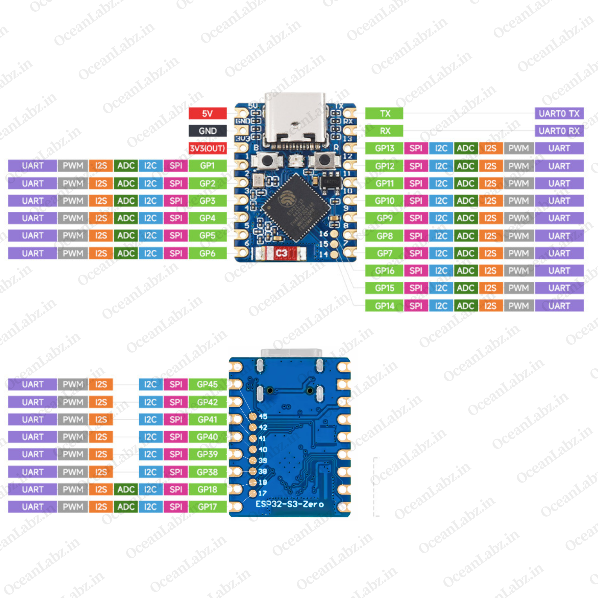 |
| ESP32-S3-Zero Pinout (Short Description): |
| Power Pins: 5V, GND, 3V3 for powering the board. Communication: Supports UART (TX/RX), I2C, SPI, and I2S. GPIOs: Configurable as PWM, ADC, UART, or digital I/O. Special Pins: GPIO8–15 for SPI/UART; GPIO17 as general-purpose. Programming: C-Type USB interface for uploading code and debugging. |
Getting Started
Hardware Preparation
To begin working with the ESP32-S3-Mini, ensure you have the following:
- ESP32-S3-Mini Module Development Board
- USB Type-C Cable
- Computer with Windows, macOS, or Linux operating system.
Software Preparation
Install Arduino IDE:
- Download and install the latest version of the Arduino IDE.
Add ESP32 Board Support:
- Open Arduino IDE and navigate to
File>Preferences.

- In the “Additional Boards Manager URLs” field, enter:
https://raw.githubusercontent.com/espressif/arduino-esp32/gh-pages/package_esp32_index.json

- Click
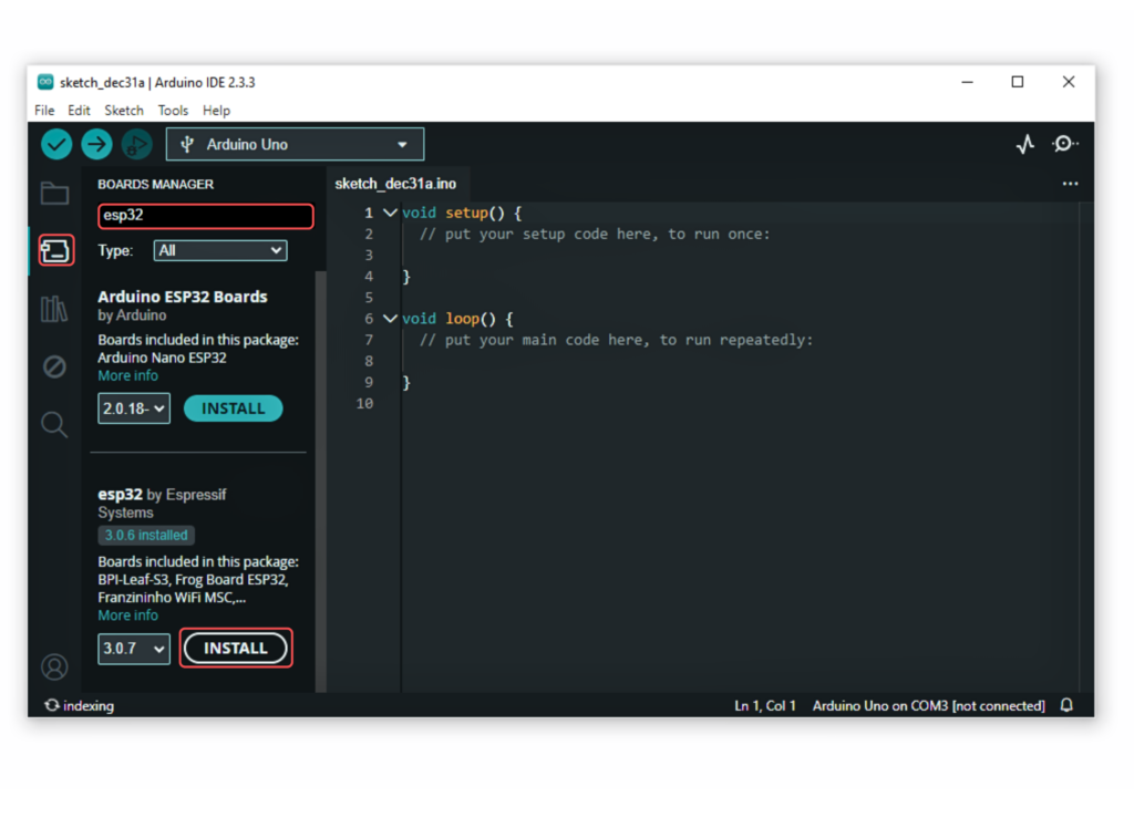
OK. - Go to the “Board manager” tab on the left-hand side of the screen.
- Click on the “Board Manager” button (Board icon) at the top of the Board tab.
- In the Board Manager window, type “esp32” in the search bar.
- Locate the “esp32” library click on the “Install” button next to it.
- Wait for the board to be installed.
Select the ESP32-S3-Mini Board:
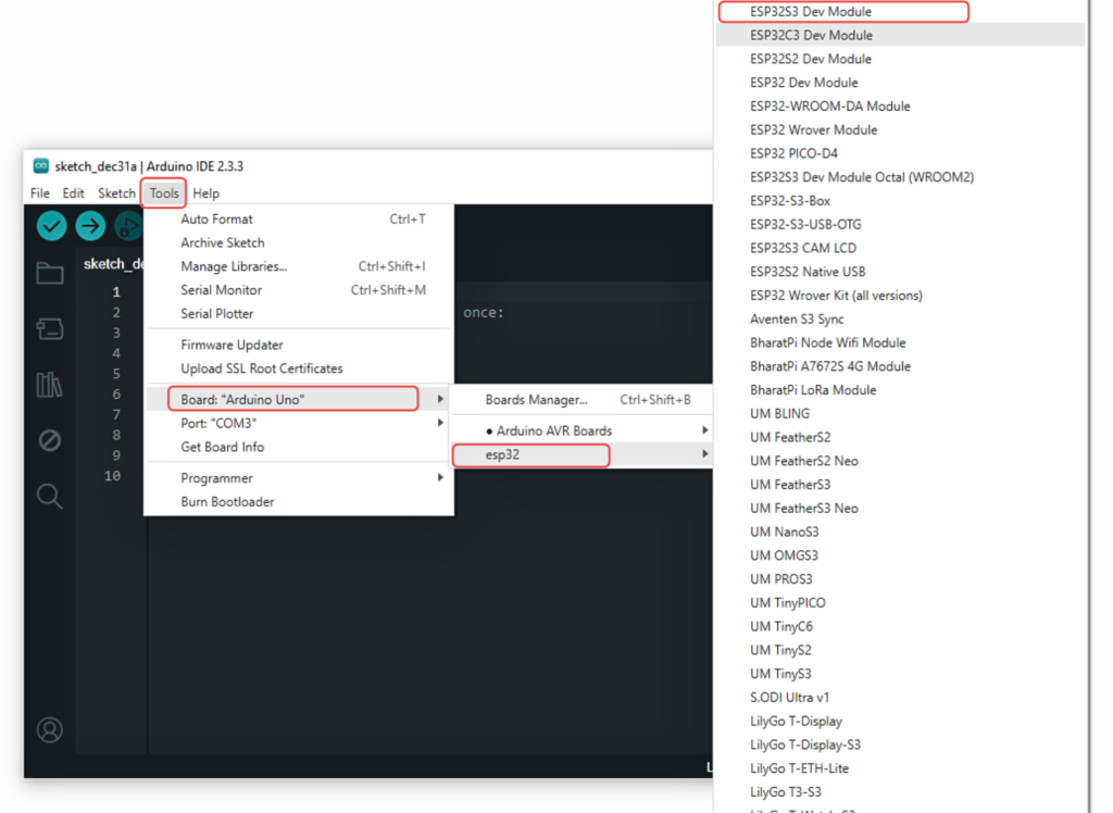
- In Arduino IDE, go to
Tools>Boardand select “ESP32S3 Dev Module” or the appropriate option for your module.
Running Your First Program
- Go to the “Libraries” tab on the left-hand side of the screen.
- Click on the “Library Manager” button (book icon) at the top of the Libraries tab.
- In the Library Manager window, type “Adafruit_NeoPixel” in the search bar.
- Locate the “Adafruit_NeoPixel” library click on the “Install” button next to it.
- Wait for the library to be installed, and you’re ready to use the Adafruit_NeoPixel library in your projects.

Use the following code
#include <Adafruit_NeoPixel.h>

#define RGB_PIN     21      // Onboard RGB LED pin
#define NUM_PIXELS  1       // Only one LED

Adafruit_NeoPixel pixel(NUM_PIXELS, RGB_PIN, NEO_GRB + NEO_KHZ800);

void setup() {
  pixel.begin();
  pixel.setBrightness(100); // Adjust brightness (0-255)
  Serial.begin(115200);

}

void loop() {
  static uint16_t hue = 0; // Hue goes from 0 to 65535 for full cycle

  // Convert HSV to RGB and set LED color
  uint32_t color = pixel.gamma32(pixel.ColorHSV(hue));
  pixel.setPixelColor(0, color);
  pixel.show();

  hue += 256; // Smooth step (smaller = slower transition)
  delay(20);  // Adjust speed of transition
  Serial.println("Hello Everyone!");
}