Index
Introduction
The ESP32-S3 DevKit-N16R8 is a powerful and feature-rich development board designed for the next generation of AIoT (Artificial Intelligence of Things) applications. With its dual-core processor, generous memory, and robust wireless capabilities, this board is perfect for makers, developers, and engineers building advanced IoT projects.
Whether you’re working with Arduino IDE, MicroPython, or ESP-IDF, this board gives you the flexibility to develop, debug, and deploy smart, connected applications with ease.
Specifications
| Feature | Details |
|---|---|
| Chipset | ESP32-S3 WROOM-N16R8 |
| Flash Memory | 16MB |
| PSRAM | 8MB |
| CPU | Dual-core LX7, 240 MHz |
| Wi-Fi | 802.11 b/g/n |
| Bluetooth | Bluetooth 5 (LE + Mesh) |
| USB Ports | Type-C (OTG + Serial) |
| GPIOs | 36, including I2C, SPI, UART, ADC |
| USB-OTG Support | Yes |
| AI Acceleration | Yes (Vector instructions) |
| Power Input | 5V via USB-C |
| Operating Voltage | 3.3V logic |
| Dimensions | Compact & breadboard-friendly |
| Headers | Unsoldered |
Features
- ESP32-S3 WROOM-N16R8 Chip: Equipped with a dual-core Xtensa® 32-bit LX7 CPU, this chip runs at up to 240 MHz, delivering reliable performance for both wireless communication and edge AI tasks.
- Memory Boost: 16MB of Flash and a generous 8MB of PSRAM provide ample space for firmware, applications, and buffering for cameras or neural network models.
- USB Type-C Dual Function: Features both USB-OTG and USB-to-Serial, enabling direct programming and peripheral interfacing without the need for extra converters.
- Wireless Connectivity: Built-in Wi-Fi (802.11 b/g/n) and Bluetooth 5 (LE) with long-range support make it ideal for mesh networking, BLE sensors, and real-time communication.
- AI Acceleration: Built-in vector instructions and hardware support for TensorFlow Lite for Microcontrollers enable on-device AI inference.
- Multiple Programming Environments: Supports Arduino, MicroPython, and ESP-IDF, giving you complete freedom over your development flow.
- Unsoldered Header Pins: Gives you flexibility to solder as needed for breadboard use or permanent installation.
Why Choose ESP32-S3 DevKit-N16R8?
This board is tailor-made for developers looking to explore the world of AI-powered embedded systems. The combination of PSRAM, USB-OTG, and BLE 5 support.
Applications
- IoT Sensors & Gateways
- AI at the Edge
- Wireless Data Logging
- BLE Beacons or Mesh Devices
- Home Automation
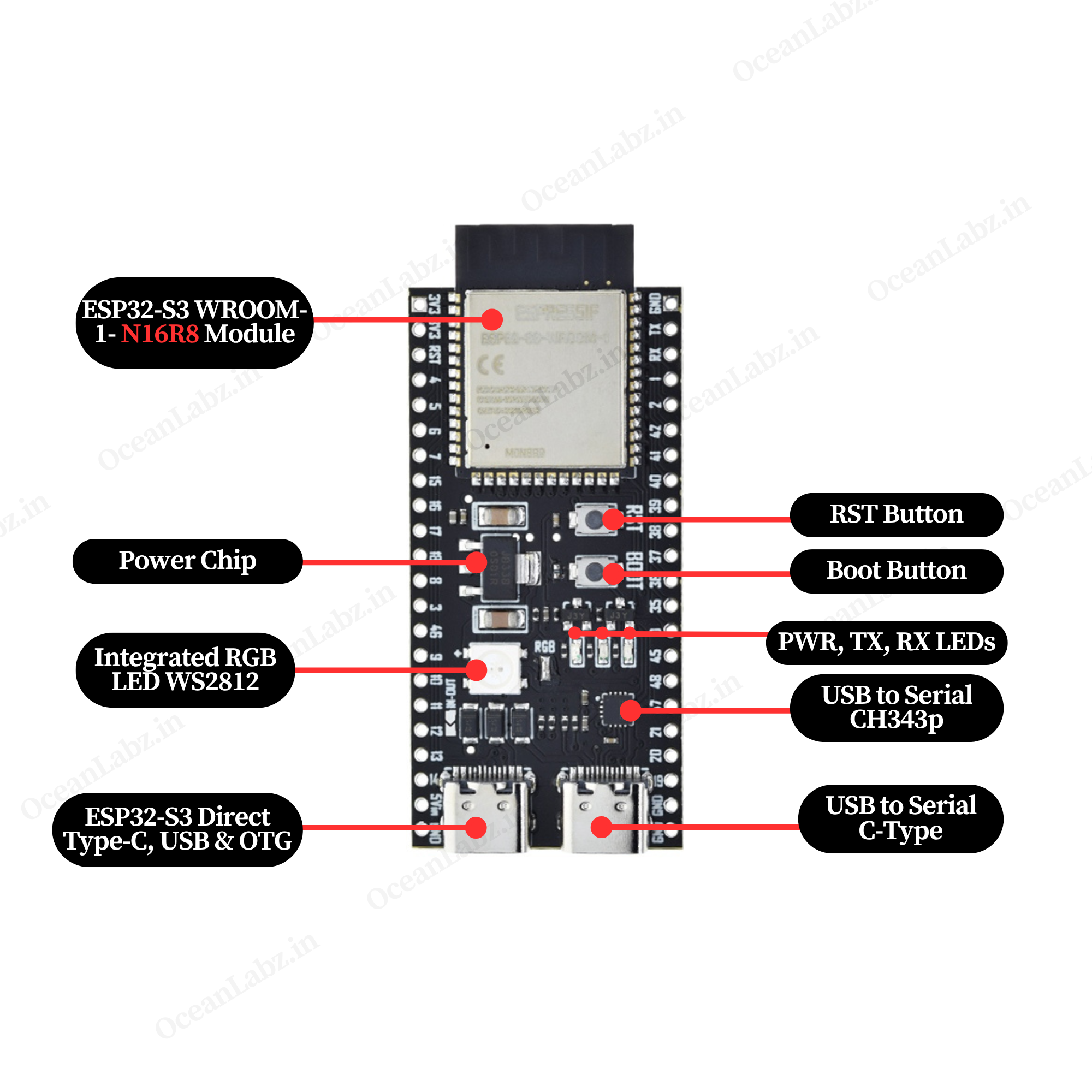
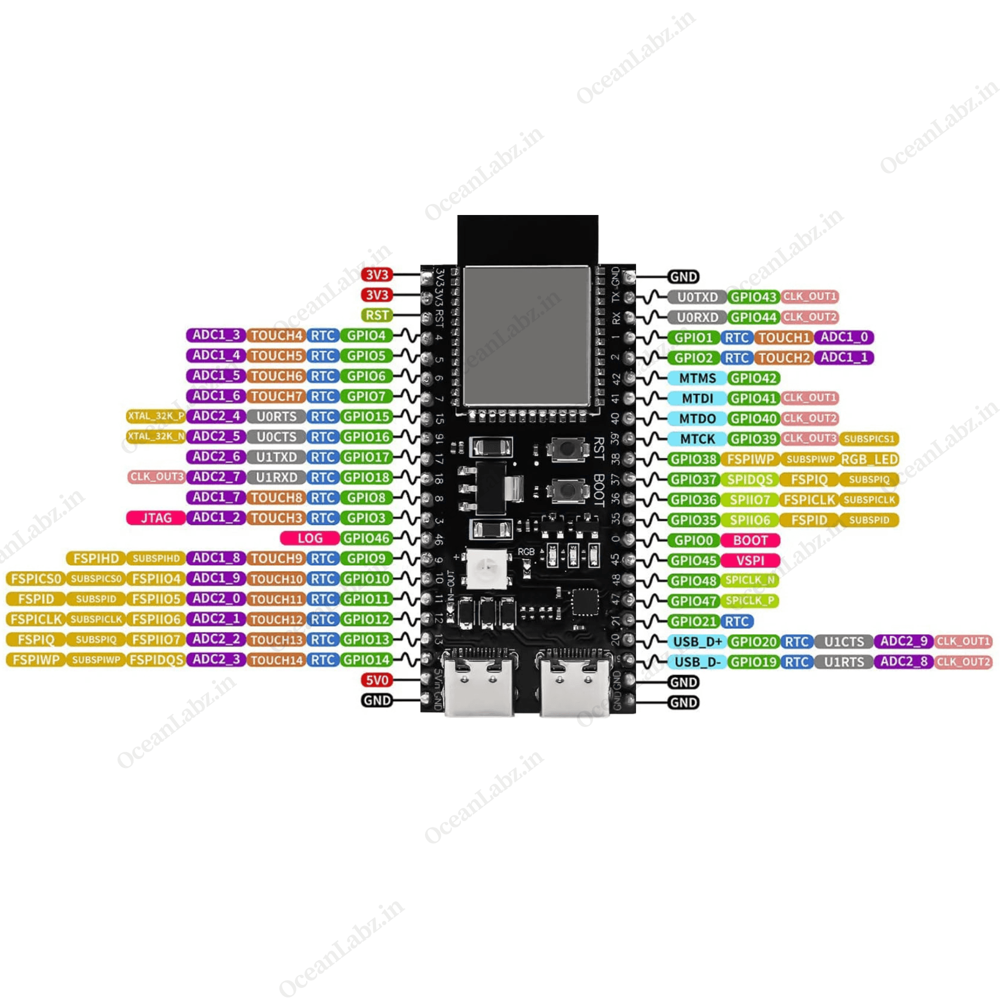
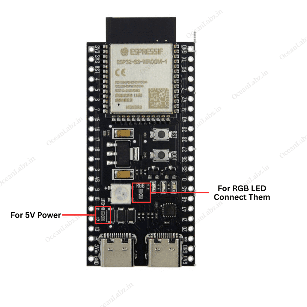
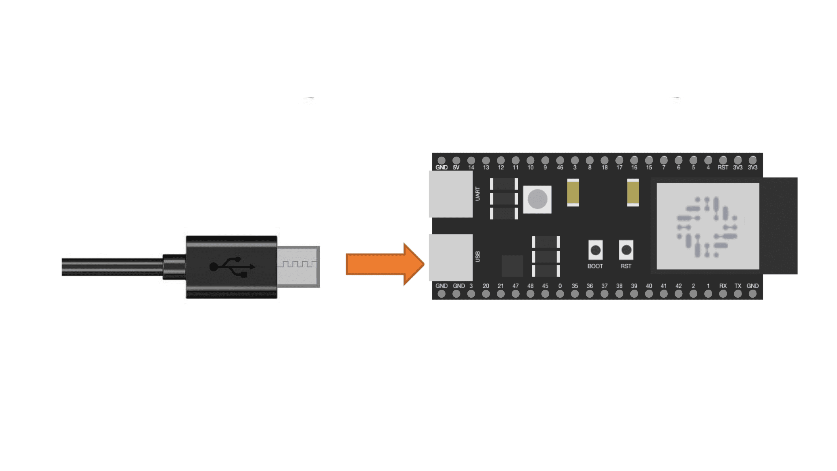
Hardware overview
| ESP32-S3 DevKit-N16R8 indication diagram |
 |
| ESP32-S3 DevKit-N16R8 Pinout Diagram |
 |
Important Note
If you’re using the 5V output or the onboard RGB LED, you need to solder two specific points on the ESP32-S3 board — one for the RGB LED and one for the 5V supply. You can refer to the image below to see the exact soldering locations.
Getting Started
Hardware Preparation
To begin working with the ESP32-S3 DevKit-N16R8, ensure you have the following:
- ESP32-S3 DevKit-N16R8 Development Board
- USB Type-C Cable
- Computer with Windows, macOS, or Linux operating system.
Software Preparation
Install Arduino IDE:
- Download and install the latest version of the Arduino IDE.
Add ESP32 Board Support:
- Open Arduino IDE and navigate to
File>Preferences.

- In the “Additional Boards Manager URLs” field, enter:
https://raw.githubusercontent.com/espressif/arduino-esp32/gh-pages/package_esp32_index.json

- Click
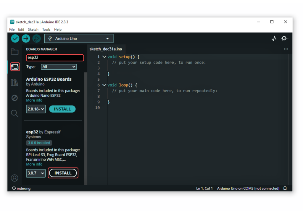
OK. - Go to the “Board manager” tab on the left-hand side of the screen.
- Click on the “Board Manager” button (Board icon) at the top of the Board tab.
- In the Board Manager window, type “esp32” in the search bar.
- Locate the “esp32” library click on the “Install” button next to it.
- Wait for the board to be installed.
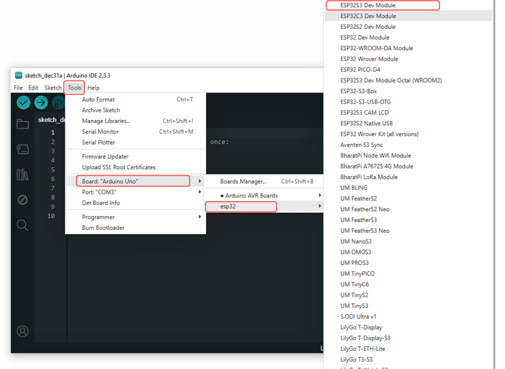
Select the ESP32-S3 Dev Module:
In Arduino IDE, go to Tools > Board and select “ESP32S3 Dev Module” or the appropriate option for your module.
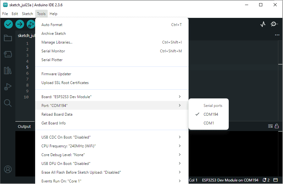
Now, connect the ESP32S3 Dev Module to your computer using a USB cable. Then, go to Tools > Port and select the COM port that the ESP32S3 Dev Module is connected to.
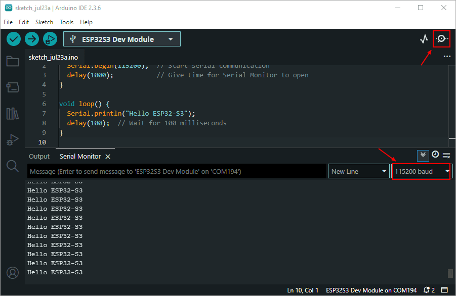
Copy the provided code into Arduino IDE, and upload it to your ESP32-S3 DevKit-N16R8.
void setup() {
  Serial.begin(115200);  // Start serial communication
  delay(1000);           // Give time for Serial Monitor to open
}

void loop() {
  Serial.println("Hello ESP32-S3");
  delay(100);  // Wait for 100 milliseconds
}
Open the Serial Monitor (Ctrl+Shift+M) and set the baud rate to 115200.
Wrapping Up
Now that you’re familiar with the ESP32-S3 DevKit N16R8 board, you’re ready to explore the world of AIoT, edge computing, and wireless innovation. Whether you’re building smart devices, experimenting with camera features, or diving into deep learning at the edge — this board is a powerful starting point.
Stay tuned for more tutorials and project ideas using ESP32-S3.