Index
Introduction
The Momentary Tactile Push Button Module is a simple and essential input device used to trigger actions when pressed.
This version includes a built-in pull-down resistor, allowing easy and direct connection to the ESP32-S3.
In this tutorial, you’ll learn how to connect the push button to an ESP32-S3 and read its state using digital input.
Required Components
- ESP32-S3 Board
- Momentary Tactile Push Button Module
- Jumper wires
- Breadboard (optional, for easier connections)
Pinout
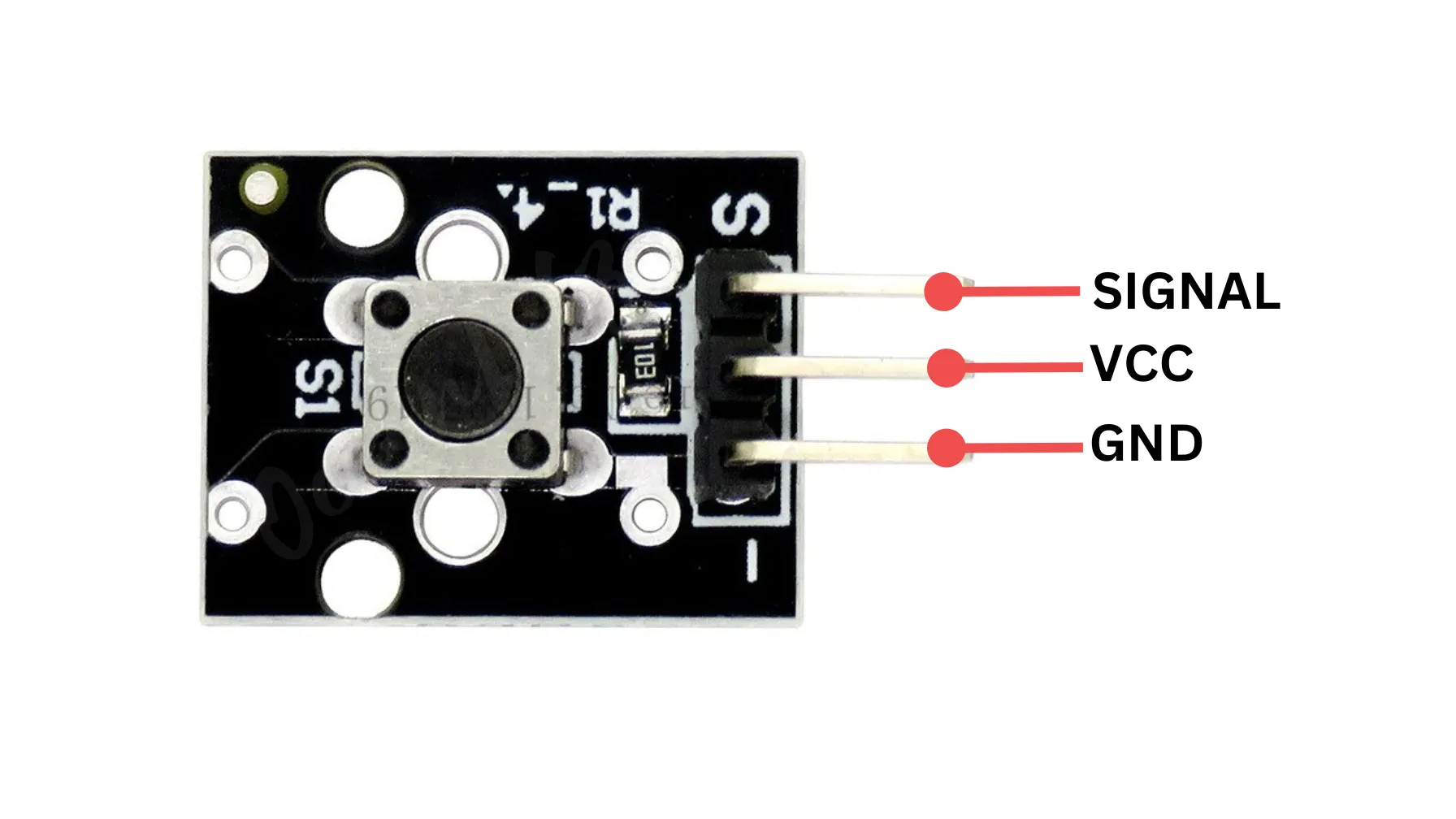
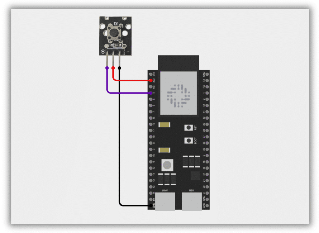
Circuit Diagram / Wiring
- Push Button VCC → VIN/5V, 3.3V (ESP32-S3)
- Push Button GND → GND (ESP32-S3)
- Push Button SIGNAL → Pin 4 (ESP32-S3)
Code / Programming
/*
Filename:     Basic_Button_Press.ino
Description:  Reads a push button with stable debounce on ESP32-S3
Author:       www.oceanlabz.in
Modification: 1/4/2025
*/

// Use a safe GPIO pin on ESP32-S3
// Example: GPIO 4
#define BUTTON_MODULE_PIN 4  // Momentary Tactile Push Button Module

void setup() {
  pinMode(BUTTON_MODULE_PIN, INPUT_PULLUP); // Use internal pull-up resistor
  Serial.begin(115200);                      // Start Serial Monitor at 115200 baud
}

void loop() {
  // Read the state of the push button
  int moduleState = digitalRead(BUTTON_MODULE_PIN);

  // Check if the button is pressed
  if (moduleState == LOW) {
    Serial.println("Module Button Pressed!");
  }

  delay(100); // Small delay for debounce
}
Explanation
- This code reads input from a momentary push button connected to ESP32-S3 using GPIO4.
- It uses internal pull-up to keep the pin HIGH until the button is pressed (goes LOW).
- When the button is pressed, “Module Button Pressed!” is printed in the Serial Monitor.
Troubleshooting
- Ensure the button is connected properly between the GPIO pin and GND.
- Double-check that GPIO 4 is not used by other hardware or restricted by the board.
- If no output appears, verify the baud rate (115200) in the Serial Monitor matches the code.