Index
Introduction
The ESP32-S3 DevKit is one of the most widely used development boards based on the ESP32-S3 chip. Unlike boards that use the ESP-WROOM-32 module, this chip offers 45 pins and comes with a different pinout configuration. In this guide, we’ll explore the ESP32-S3 DevKit pinout and break down the key functions of its GPIO pins.
ESP32-S3 Peripherals and I/O
The ESP32-S3 comes with a rich set of peripherals, including:
- 20 Analog-to-Digital Converter (ADC) channels
- 4 SPI interfaces
- 3 UART interfaces
- 2 I2C interfaces
- 8 PWM output channels
- 2 I2S interfaces
- 14 Capacitive sensing GPIOs
Thanks to the ESP32’s GPIO multiplexing capability, you can map almost any function to the GPIO pins of your choice. However, some pins come with default functions pre-assigned. In this pinout, we’ll explore both the default mappings and the flexibility you have when configuring them.
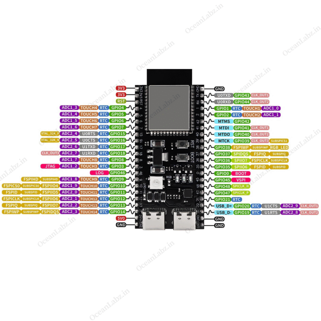
ESP32-S3 Pinout
The image below illustrates the pinout of the ESP32-S3 DevKit board, one of the most widely used development boards based on the ESP32-S3 chip. Keep in mind that there are multiple versions of this board, and their pinouts may vary slightly. Always verify the pin locations and GPIO labels before connecting any peripherals to ensure proper functionality.
SPI Flash and PSRAM
- GPIOs 26 to 32 are internally connected to the integrated SPI flash and PSRAM.
- These pins are not recommended for general use.
- On the ESP32-S3 DevKit, they are usually not exposed, but if available on other boards, avoid using them:
| GPIO | Function |
|---|---|
| 26 | Flash/PSRAM SPICS1 |
| 27 | Flash/PSRAM SPIHD |
| 28 | Flash/PSRAM SPIWP |
| 29 | Flash/PSRAM SPICS0 |
| 30 | Flash/PSRAM SPICLK |
| 31 | Flash/PSRAM SPIQ |
| 32 | Flash/PSRAM SPID |
Capacitive Touch GPIOs
- The ESP32-S3 has 14 internal capacitive touch pins.
- They can sense changes in electrical charge (like when touched by a finger).
- Useful for creating touch buttons or as a wake-up source from deep sleep.
| Touch Pin | GPIO |
|---|---|
| T1 | 1 |
| T2 | 2 |
| T3 | 3 |
| T4 | 4 |
| T5 | 5 |
| T6 | 6 |
| T7 | 7 |
| T8 | 8 |
| T9 | 9 |
| T10 | 10 |
| T11 | 11 |
| T12 | 12 |
| T13 | 13 |
| T14 | 14 |
Analog-to-Digital Converter (ADC)
- 20 channels with 12-bit resolution (0–4095 values).
- 0 = 0V, 4095 = 3.3V.
- Can configure resolution and range in code.
ADC1 Channels: GPIO 1–10
ADC2 Channels: GPIO 11–20
RTC GPIOs
- These pins can be used in deep sleep mode with the RTC (Real-Time Clock) subsystem.
- Can wake the ESP32-S3 when the ULP coprocessor is active.
RTC GPIOs: 0–21
PWM (LED Control)
- ESP32-S3 has an 8-channel PWM controller.
- Any output-capable GPIO can generate PWM signals.
- Parameters: frequency, duty cycle, channel, and pin.
I2C
- Default pins in Arduino IDE:
- GPIO 8 = SDA
- GPIO 9 = SCL
- Can be reassigned to other pins if needed.
SPI
- ESP32-S3 has 4 SPI buses: SPI0, SPI1 (internal), HSPI (SPI2), VSPI (SPI3).
- Only HSPI and VSPI should be used by users.
| Bus | MOSI | MISO | CLK | CS |
|---|---|---|---|---|
| HSPI | 11 | 13 | 12 | 10 |
| VSPI | 35 | 37 | 36 | 39 |
UART (Serial)
- Supports up to 3 UART interfaces.
- Default mapping:
| UART | TX | RX | Notes |
|---|---|---|---|
| 0 | GPIO 43 | GPIO 44 | Fixed, for programming & debugging |
| 1 | GPIO 17 | GPIO 18 | Can be reassigned |
| 2 | Any | Any | Fully customizable |
Strapping Pins
- Used for bootloader/flash mode. Avoid using them in projects.
- GPIO 0, 3, 45, 46
Enable (EN/RST)
- Connected to the 3.3V regulator enable pin.
- Pulling low resets the chip.
- Can be connected to a push button for manual reset.
Wrapping Up
We hope this ESP32-S3 GPIO reference guide has been helpful. If you have additional tips, tricks, or best practices for using ESP32-S3 GPIOs, feel free to share them in the comments below — your insights might help other makers and developers!