Index
Introduction
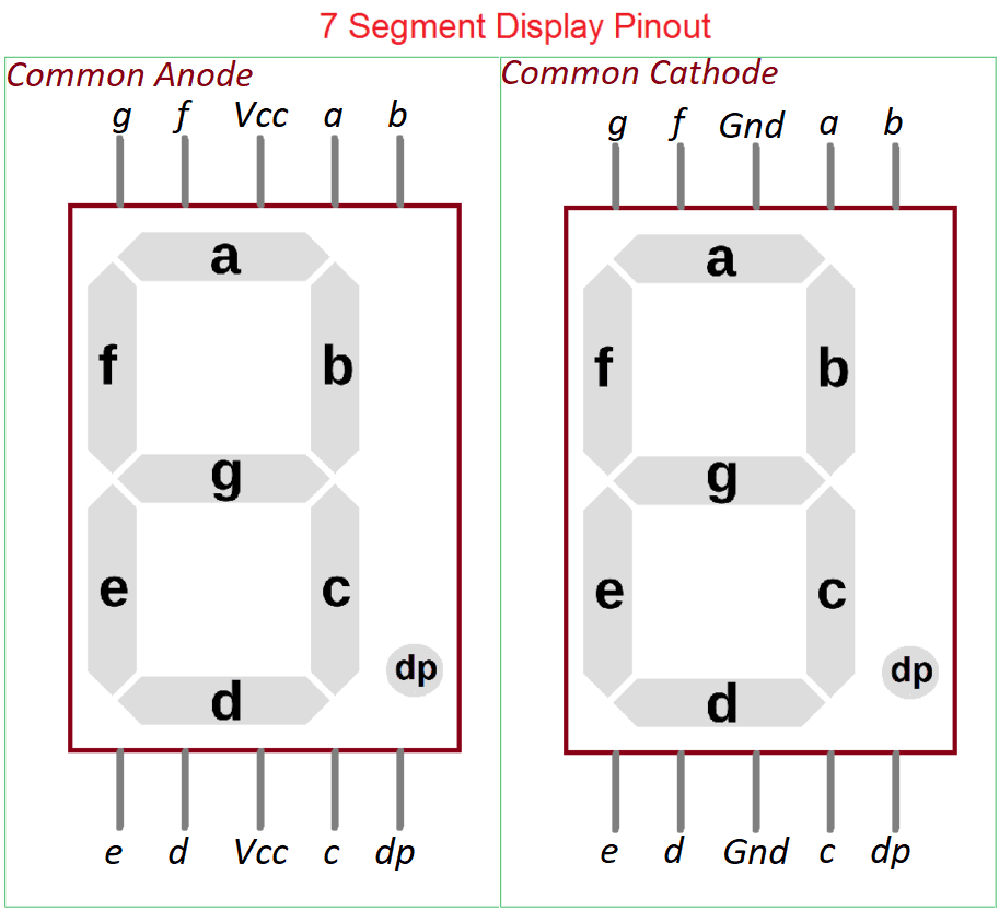
A 7-segment display is used to show numeric digits using 7 LEDs (segments) labeled a–g.
Each segment is controlled individually to display numbers from 0 to 9.
Available in Common Cathode or Common Anode types.
In this tutorial, we’ll connect and control a 1-digit 7-segment display using the ESP32-S3.
Required Components
- ESP32-S3 Board
- 7 Segment Display
- 220 Ohm Resistor
- Jumper wires
- Breadboard
Pinout
To use a single-digit 7-segment display, you can choose between two types: Common Anode (CA) and Common Cathode (CC). Both work similarly by lighting up the segments when properly biased. The main difference lies in the polarity of the connection, so you can select either type depending on your circuit’s output configuration and requirements.
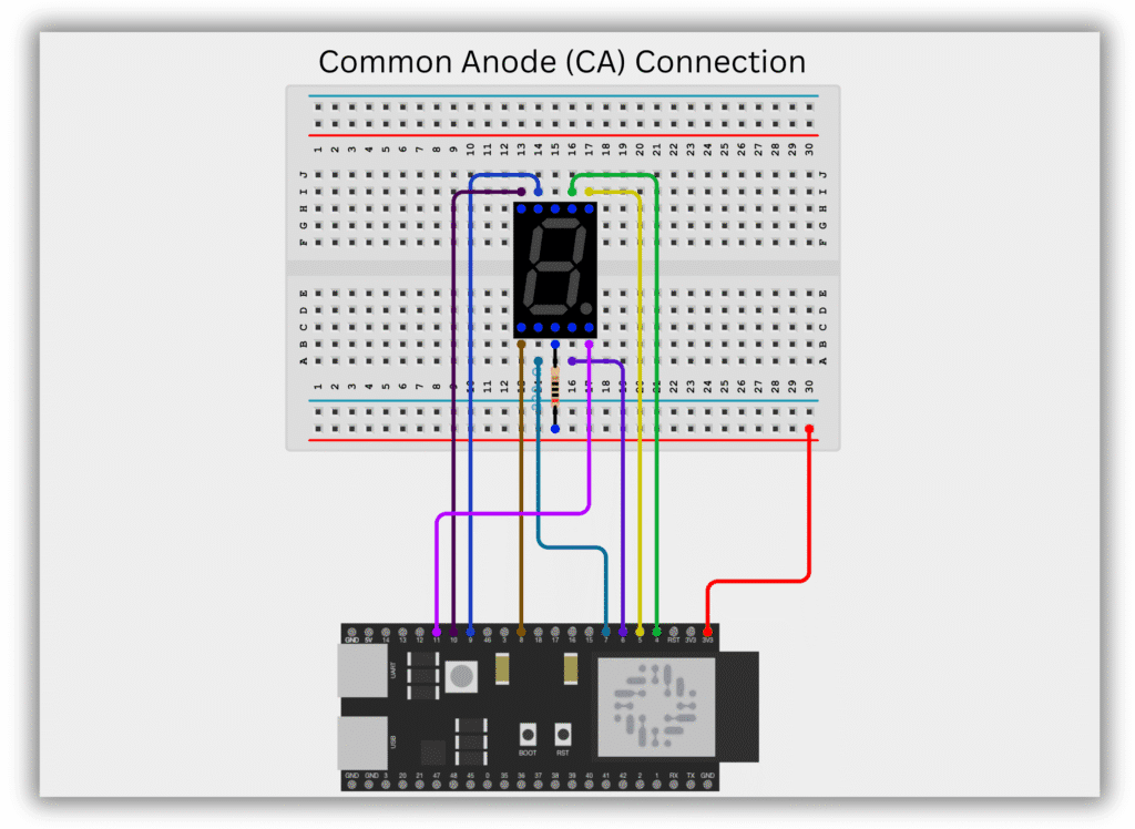
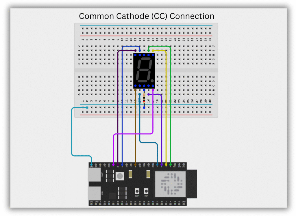
Circuit Diagram / Wiring
- Segment (a) → ESP32-S3 GPIO 4
- Segment (b) → ESP32-S3 GPIO 5
- Segment (c) → ESP32-S3 GPIO 6
- Segment (d) → ESP32-S3 GPIO 7
- Segment (e) → ESP32-S3 GPIO 8
- Segment (f) → ESP32-S3 GPIO 9
- Segment (g) → ESP32-S3 GPIO 10
- Segment (dp) → ESP32-S3 GPIO 11
- Segment (GND) → ESP32-S3 GND
- Common Anode (VCC) → ESP32-S3 3.3V or 5V with Resistor 220 Ohm
- Common Cathode (GND) → ESP32-S3 GND with Resistor 220 Ohm
Code / Programming
/*
  Filename: ESP32-S3_7segment_display_with_dp.ino
  Description: Display digits 0–9 on a 7-segment display (Common Cathode or Anode) using ESP32-S3 with DP control
  Author: www.oceanlabz.in
  Modification: 1/4/2025
*/

// Choose type: "CC" for Common Cathode, "CA" for Common Anode
String commonType = "CC";  // Change to "CA" if you're using Common Anode

// Define ESP32-S3 GPIO pins connected to segments a-g and DP
const int a = 4;
const int b = 5;
const int c = 6;
const int d = 7;
const int e = 8;
const int f = 9;
const int g = 10;
const int dp = 11;  // Decimal point pin

// Segment patterns for digits 0 to 9 (Standard pattern)
byte digits[10][7] = {
  // a, b, c, d, e, f, g
  {1, 1, 1, 1, 1, 1, 0},  // 0
  {0, 1, 1, 0, 0, 0, 0},  // 1
  {1, 1, 0, 1, 1, 0, 1},  // 2
  {1, 1, 1, 1, 0, 0, 1},  // 3
  {0, 1, 1, 0, 0, 1, 1},  // 4
  {1, 0, 1, 1, 0, 1, 1},  // 5
  {1, 0, 1, 1, 1, 1, 1},  // 6
  {1, 1, 1, 0, 0, 0, 0},  // 7
  {1, 1, 1, 1, 1, 1, 1},  // 8
  {1, 1, 1, 1, 0, 1, 1}   // 9
};

// Segment pin array a–g
const int segmentPins[7] = {a, b, c, d, e, f, g};

void setup() {
  for (int i = 0; i < 7; i++) {
    pinMode(segmentPins[i], OUTPUT);
  }

  pinMode(dp, OUTPUT);
  digitalWrite(dp, LOW);  // Turn off decimal point at start
}

void loop() {
  for (int i = 0; i < 10; i++) {
    displayDigit(i);

    // Blink decimal point
    digitalWrite(dp, getLogicLevel(1));
    delay(500);
    digitalWrite(dp, getLogicLevel(0));
    delay(500);
  }
}

// Function to display digits 0–9
void displayDigit(int num) {
  for (int i = 0; i < 7; i++) {
    digitalWrite(segmentPins[i], getLogicLevel(digits[num][i]));
  }
}

// Invert signal if Common Anode
int getLogicLevel(int value) {
  if (commonType == "CA") {
    return value == 1 ? LOW : HIGH;  // Invert logic for CA
  } else {
    return value == 1 ? HIGH : LOW;  // Normal logic for CC
  }
}
Explanation
- This code controls a 7-segment display (Common Cathode or Common Anode) using an ESP32-S3.
- You can switch display types by setting
commonTypeto"CC"or"CA"in the code. - It displays digits 0–9 with blinking decimal point (DP) using GPIO pins 4–11.
Troubleshooting
- If no digit appears, double-check the wiring of each segment pin (a–g, DP) and ensure correct GPIO mapping.
- For incorrect or inverted display, make sure you’ve set
commonTypecorrectly to"CC"(Common Cathode) or"CA"(Common Anode). - If DP (decimal point) doesn’t blink, confirm the DP pin is connected properly and controlled via GPIO 11.