Index
Introduction
In this tutorial, we will learn how to display custom animations on an 8×8 LED matrix using the MAX7219 module and ESP32-S3.
We’ll show different patterns like a face, heart, and smiley by controlling each row of LEDs.
This project uses the MD_MAX72xx library, which makes it easy to control LED matrices.
It’s a fun and beginner-friendly way to understand how LED displays work with microcontrollers.
Required Components
- ESP32-S3 Board
- 8×8 LED Matrix Display Module
- Jumper wires
- Breadboard
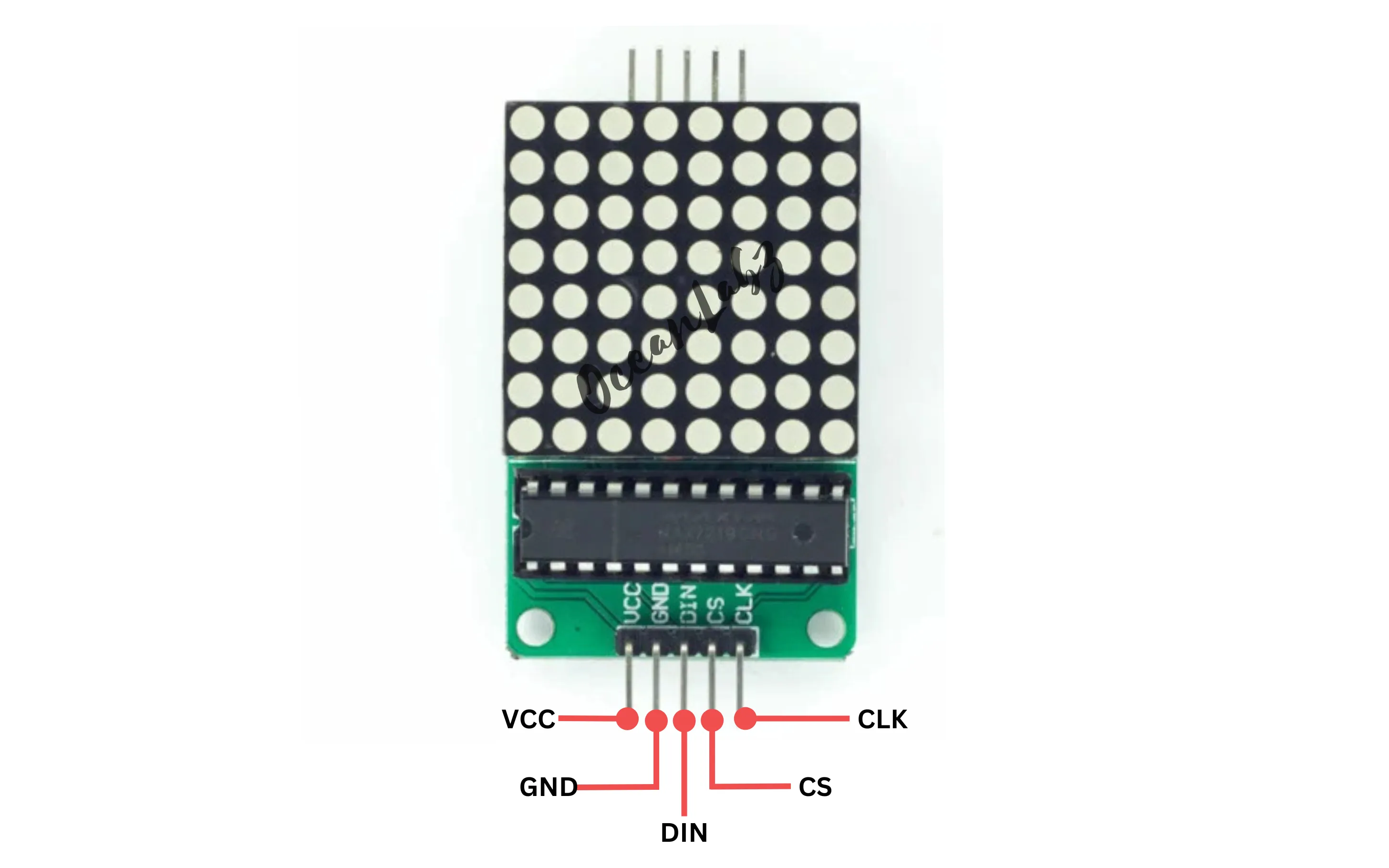
Pinout
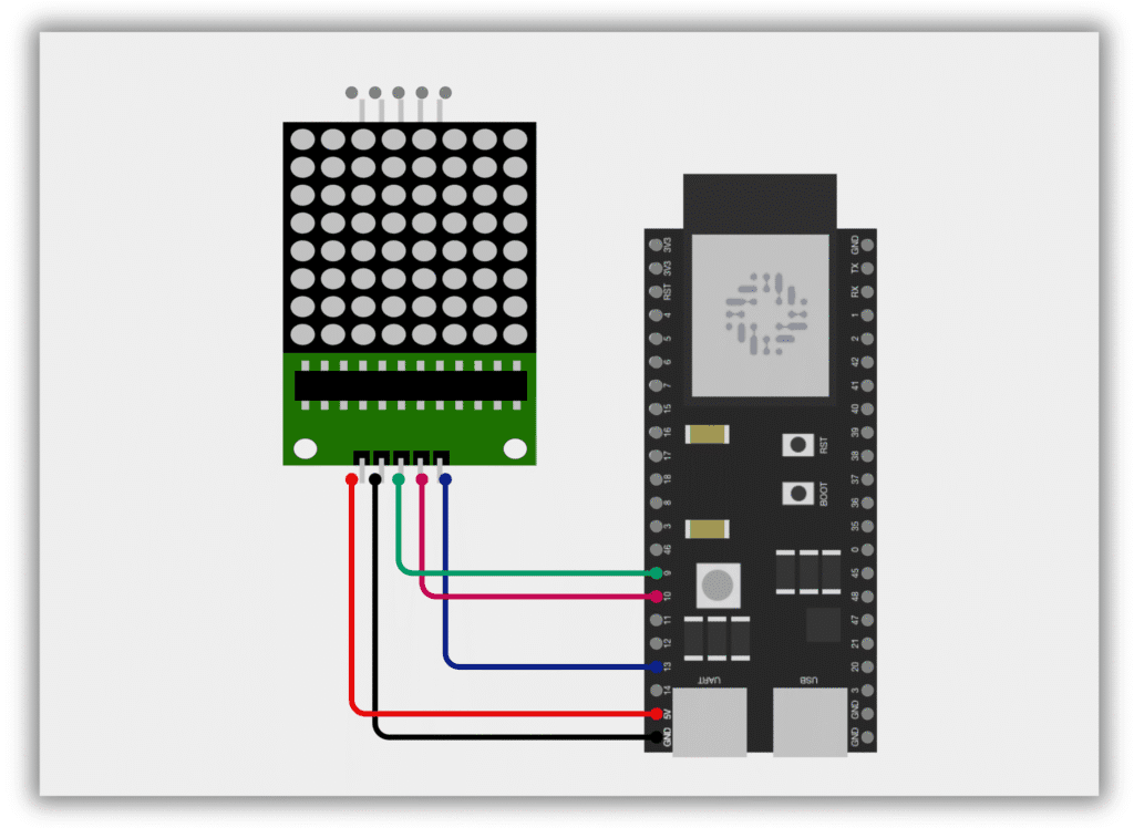
Circuit Diagram / Wiring
- VCC (LED Module) → VIN/5V (ESP32-S3)
- GND (LED Module) → GND (ESP32-S3)
- DIN (LED Module) → Pin 9(ESP32-S3)
- CS (LED Module) → Pin 10(ESP32-S3)
- CLK (LED Module) → Pin 13(ESP32-S3)
Code / Programming
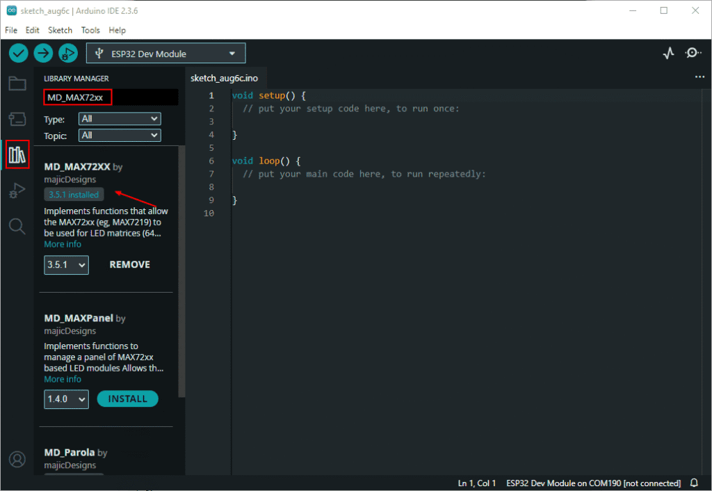
- Install Required Library (via Arduino Library Manager).
- Go to the “Libraries” tab on the left-hand side of the screen.
- Click on the “Library Manager” button (book icon) at the top of the Libraries tab.
- In the Library Manager window, type “MD_MAX72xx” in the search bar.
- Locate the “MD_MAX72xx” library click on the “Install” button next to it.
- Wait for the library to be installed, and you’re ready to use the MD_MAX72xx library in your projects.
/*
  Filename: ESP32-S3_led_matrix_display.ino
  Description: Displays animated patterns (face, heart, smiley) on 8x8 LED matrix using MAX7219 and ESP32-S3
  Author: www.oceanlabz.in
  Modified: 1/4/2025
*/

#include <MD_MAX72xx.h>
#include <SPI.h>

// Define hardware type and connections
#define HARDWARE_TYPE MD_MAX72XX::FC16_HW
#define DATA_PIN  9   // DIN
#define CLK_PIN   13   // CLK
#define CS_PIN    10    // LOAD/CS
#define MAX_DEVICES 1  // Number of 8x8 matrices

MD_MAX72XX matrix = MD_MAX72XX(HARDWARE_TYPE, DATA_PIN, CLK_PIN, CS_PIN, MAX_DEVICES);

// Predefined patterns
byte normalFace[8] = {
  B00111100,
  B01000010,
  B10100101,
  B10000001,
  B10000001,
  B10111101,
  B01000010,
  B00111100
};

byte heart[8] = {
  B00000000,
  B01100110,
  B11111111,
  B11111111,
  B11111111,
  B01111110,
  B00111100,
  B00011000
};

byte smileFace[8] = {
  B00111100,
  B01000010,
  B10100101,
  B10000001,
  B10100101,
  B10011001,
  B01000010,
  B00111100
};

void setup() {
  matrix.begin();
  matrix.control(MD_MAX72XX::INTENSITY, 8); // Brightness 0–15
  matrix.clear();
}

void loop() {
  showPattern(normalFace);
  delay(1000);
  matrix.clear();
  delay(300);

  showPattern(heart);
  delay(1000);
  matrix.clear();
  delay(300);

  showPattern(smileFace);
  delay(1000);
  matrix.clear();
  delay(300);
}

// Show an 8x8 pattern on the LED matrix
void showPattern(byte* pattern) {
  for (int row = 0; row < 8; row++) {
    matrix.setRow(0, row, pattern[row]);
  }
}
Explanation
- This code uses the MD_MAX72xx library to control an 8×8 LED matrix (MAX7219) with the ESP32-S3.
- It displays three predefined patterns: a normal face, a heart, and a smiley face in a loop with delays.
- The
showPattern()function sends 8-byte arrays to the LED matrix to light up rows accordingly.
Troubleshooting
- Make sure the MD_MAX72xx library is installed from the Library Manager, not LedControl (which doesn’t support ESP32 well).
- Double-check the wiring: DIN to GPIO 9, CLK to GPIO 13, and CS to GPIO 10 (or adjust to match your wiring).
- Ensure the matrix module is MAX7219-based and powered properly (use external 5V if needed).