Index
Introduction
The Blinking LED project is the simplest and most effective way to get started with the ESP32-S3 DevKit-N16R8 Board. It introduces you to the concept of digital output control through code. In this beginner-friendly project, we use one of the digital GPIO pins on the ESP32-S3 to blink an LED by turning it on and off at regular intervals.
Required Components
- ESP32-S3 Board
- LED
- 220Ω Resistor
- Jumper Wires
- Breadboard
Pinout
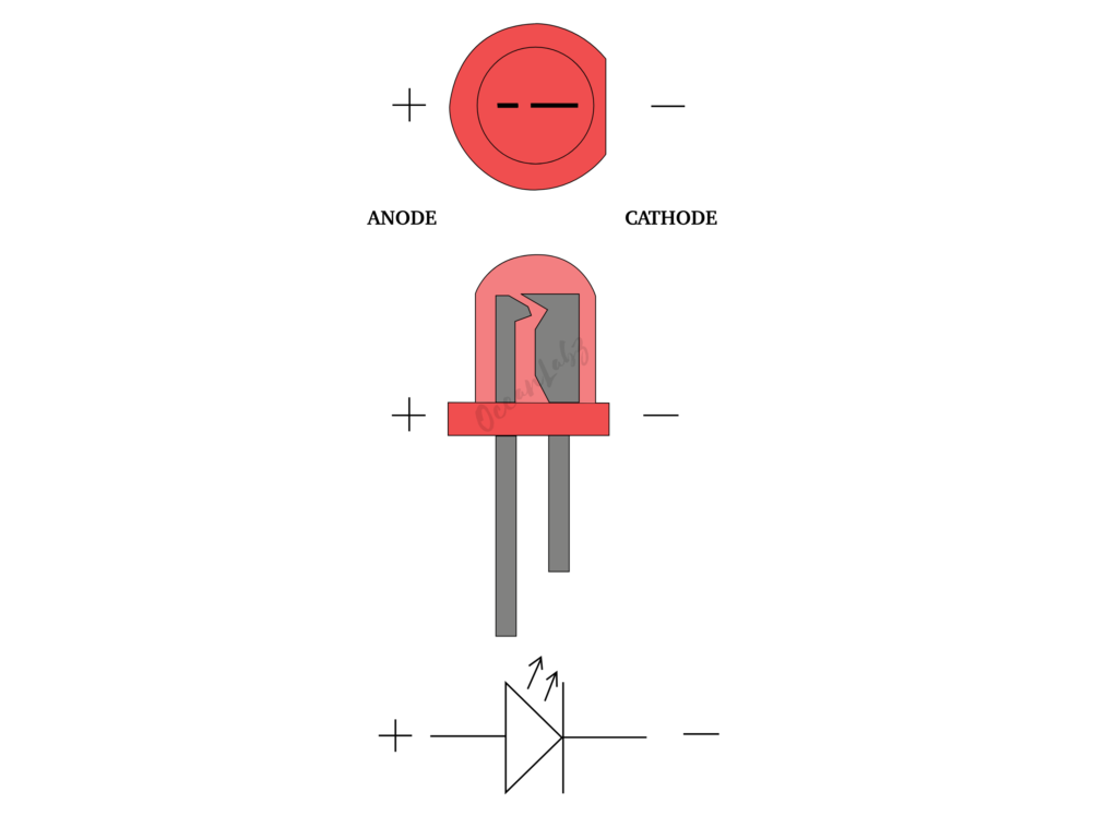
- LED Anode (+)
- LED Cathode (-)
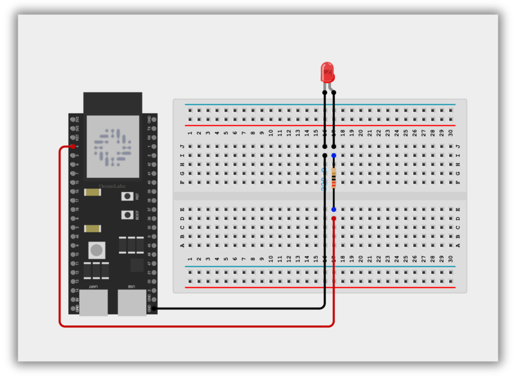
Circuit Diagram
- ESP32 GPIO 4 → 220Ω Resistor → LED (Anode +)
- ESP32 GND → LED (Cathode -)
Code / Programming
/*
Filename: ol_blink_LED.ino
Description: Simple LED blink code for ESP32-S3. Blinks an LED connected to GPIO4 every second.
Author: www.oceanlabz.in
Modification: 1/4/2025
*/

#define LED_PIN 4  // Define LED pin

void setup() {
  pinMode(LED_PIN, OUTPUT);  // Set LED pin as output
}

void loop() {
  digitalWrite(LED_PIN, HIGH);  // Turn LED ON
  delay(1000);                  // Wait 1 second
  digitalWrite(LED_PIN, LOW);   // Turn LED OFF
  delay(1000);                  // Wait 1 second
}
Explanation
- Sets GPIO 4 as an output pin to control an LED.
- In the
loop(), turns the LED ON for 1 second and then OFF for 1 second. - Repeats this cycle endlessly to create a blinking effect.
Troubleshooting
- Check LED wiring: GPIO 4 → Resistor → Anode (+), Cathode (–) → GND.
- Ensure correct board & COM port in Arduino IDE; use a data-capable USB cable.
- If GPIO 4 doesn’t work, try GPIO 5 or 48; press BOOT during upload if needed.