Index
Introduction
In this lesson, we will learn about the NOR gate, an important logic gate in digital electronics.
A NOR gate is the inverse of the OR gate.
It gives an output HIGH (1) only when ALL inputs are LOW (0).
If any input becomes HIGH, the output turns LOW.
NOR gates are also called Universal Gates, just like NAND gates.
What Is a NOR Gate?
A NOR gate is a two-input logic gate.
Simple meaning:
Output is ON only when Input A NOR Input B are OFF.
Truth Table of NOR Gate
| Input A | Input B | Output |
|---|---|---|
| 0 | 0 | 1 |
| 0 | 1 | 0 |
| 1 | 0 | 0 |
| 1 | 1 | 0 |
Output is HIGH only when both inputs are LOW.
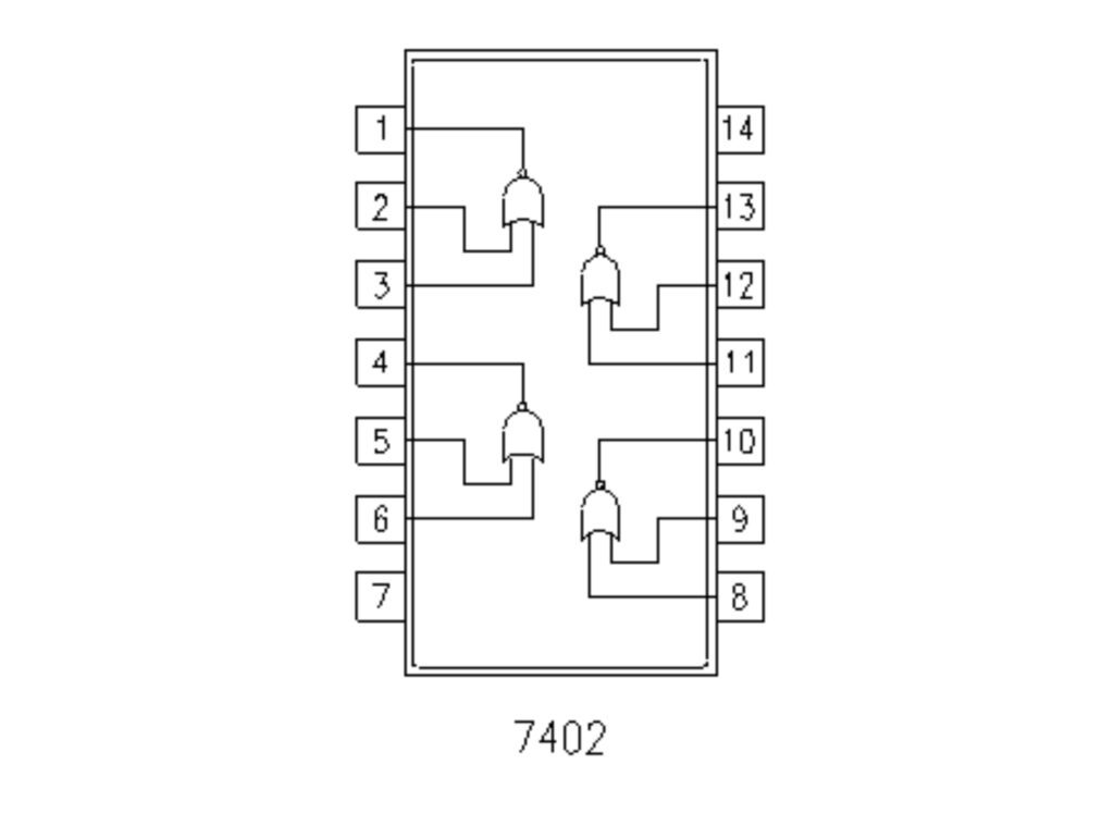
IC 7402 – Quad 2-Input NOR Gate
IC 7402 contains four NOR gates inside one IC.
Key Features:
- 4 independent NOR gates
- Operates at 5V
- TTL logic IC (74xx family)
- Widely used in digital systems
IC 7402 Pin Configuration
| Pin | Function |
|---|---|
| 1 | Output Y1 |
| 2 | Input A1 |
| 3 | Input B1 |
| 4 | Output Y2 |
| 5 | Input A2 |
| 6 | Input B2 |
| 7 | GND |
| 8 | Input A3 |
| 9 | Input B3 |
| 10 | Output Y3 |
| 11 | Input A4 |
| 12 | Input B4 |
| 13 | Output Y4 |
| 14 | VCC (5V) |
Why Is NOR Gate Important?
NOR gates are used when:
- Output must stay HIGH only in idle state
- Active-LOW logic is required
- Control systems need inverted OR behavior
NOR is also a universal gate, meaning all logic gates can be built using NOR gates alone.
Components Required
| Component | Quantity | Purpose |
|---|---|---|
| IC 7402 | 1 | NOR logic |
| Push Buttons | 2 | Input control |
| LED | 1 | Output indication |
| 220Ω Resistor | 1 | LED protection |
| Breadboard | 1 | Circuit building |
| Jumper Wires | As required | Connections |
| 5V Power Supply | 1 | Power source |
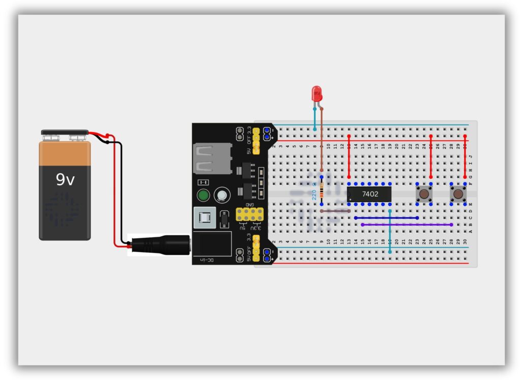
Circuit Diagram / Wiring
- Place IC 7402 on the breadboard
- Connect Pin 14 to +5V
- Connect Pin 7 to GND
- Connect Push Button 1 to Pin 2 (Input A)
- Connect Push Button 2 to Pin 3 (Input B)
- Connect Pin 1 (Output) to LED through 220Ω resistor
- Connect LED’s other end to GND
Working Principle
Case 1: No Button Pressed (0,0)
- Output = HIGH
- LED ON
Case 2: Any One Button Pressed (1,0 or 0,1)
- Output = LOW
- LED OFF
Case 3: Both Buttons Pressed (1,1)
- Output = LOW
- LED OFF
This confirms NOR gate behavior.
Observation Table
| Button A | Button B | Output | LED |
|---|---|---|---|
| OFF | OFF | 1 | ON |
| ON | OFF | 0 | OFF |
| OFF | ON | 0 | OFF |
| ON | ON | 0 | OFF |
Common Mistakes & Troubleshooting
❌ LED always OFF
✔ Check if both inputs are LOW
❌ IC not working
✔ Verify VCC and GND pins
❌ Flickering LED
✔ Inputs may be floating
Real-Life Applications
- Control logic circuits
- Digital memory elements
- Alarm systems
- Industrial automation
- Signal processing