Index
Introduction
In this lesson, we will learn about the OR gate, one of the fundamental logic gates used in digital electronics.
An OR gate gives an output HIGH (1) when any one or more inputs are HIGH.
The output becomes LOW only when all inputs are LOW.
This lesson will help you understand:
- How OR logic works
- How IC 7432 functions
- How to build an OR gate circuit using push buttons and an LED
What Is an OR Gate?
An OR gate is a two-input logic gate.
Simple meaning:
Output is ON if Input A OR Input B is ON.
Real-life example:
- A bell rings if Front Door OR Back Door is opened
- A fan turns ON if Manual Switch OR Automatic Sensor is active
Truth Table of OR Gate
| Input A | Input B | Output |
|---|---|---|
| 0 | 0 | 0 |
| 0 | 1 | 1 |
| 1 | 0 | 1 |
| 1 | 1 | 1 |
Output is HIGH when any input is HIGH.
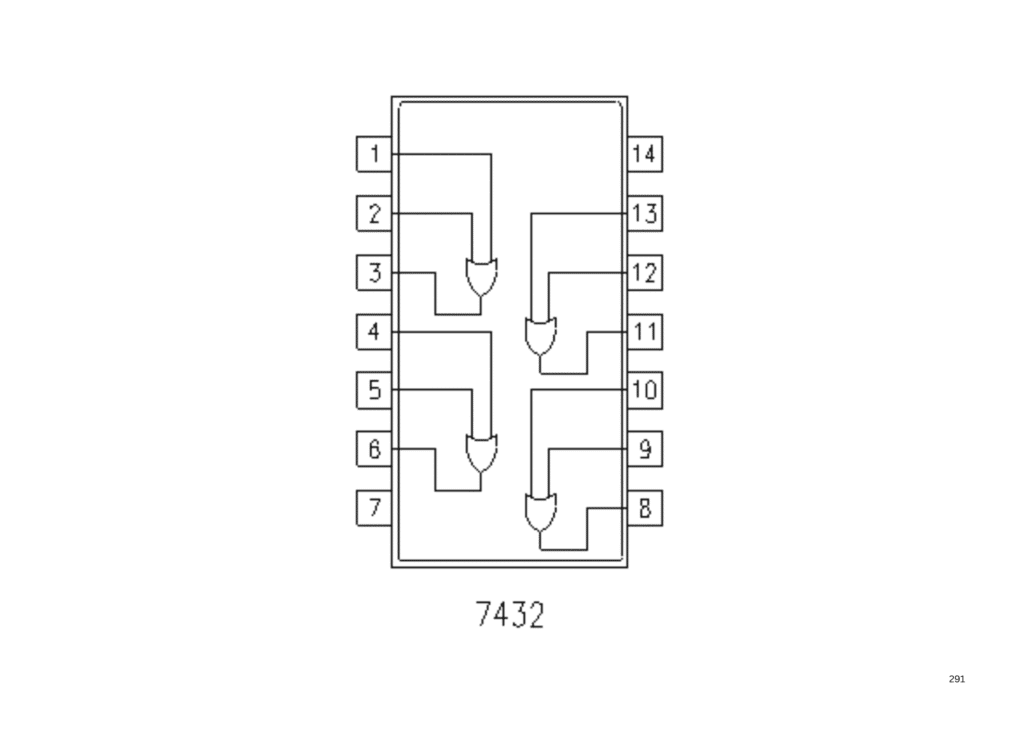
IC 7432 – Quad 2-Input OR Gate
IC 7432 contains four OR gates inside one IC.
Key Features:
- 4 independent OR gates
- Operates at 5V
- TTL logic IC (74xx family)
- Easy to use for beginners
IC 7432 Pin Configuration
| Pin | Function |
|---|---|
| 1 | Input A1 |
| 2 | Input B1 |
| 3 | Output Y1 |
| 4 | Input A2 |
| 5 | Input B2 |
| 6 | Output Y2 |
| 7 | GND |
| 8 | Output Y3 |
| 9 | Input A3 |
| 10 | Input B3 |
| 11 | Output Y4 |
| 12 | Input A4 |
| 13 | Input B4 |
| 14 | VCC (5V) |
Why Do We Use an OR Gate?
OR gates are used when:
- Multiple ways can activate one output
- Backup or alternative conditions are needed
- Redundant control logic is required
Example uses:
- Emergency systems
- Alarm triggering
- Power backup logic
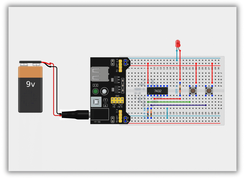
Components Required
| Component | Quantity | Purpose |
|---|---|---|
| IC 7432 | 1 | OR logic |
| Push Buttons | 2 | Input control |
| LED | 1 | Output indication |
| 220Ω Resistor | 1 | LED protection |
| 10K Resistor | 2 | Input control |
| Breadboard | 1 | Circuit building |
| Jumper Wires | As required | Connections |
| 5V Power Supply | 1 | Power source |
Circuit Diagram / Wiring
- Place IC 7432 on the breadboard
- Connect Pin 14 to +5V
- Connect Pin 7 to GND
- 10kΩ resistor from Pin 1 (Input A) → GND
- 10kΩ resistor from Pin 2 (Input B) → GND
- Connect Push Button 1 to Pin 1 (Input A)
- Connect Push Button 2 to Pin 2 (Input B)
- Connect Pin 3 (Output) to LED through a 220Ω resistor
- Connect LED’s other end to GND
Working Principle
Case 1: No Button Pressed (0,0)
- Output = LOW
- LED OFF
Case 2: Any One Button Pressed (1,0 or 0,1)
- Output = HIGH
- LED ON
Case 3: Both Buttons Pressed (1,1)
- Output = HIGH
- LED ON
This verifies the OR gate operation.
Observation Table
| Button A | Button B | Output | LED |
|---|---|---|---|
| OFF | OFF | 0 | OFF |
| ON | OFF | 1 | ON |
| OFF | ON | 1 | ON |
| ON | ON | 1 | ON |
Common Mistakes & Troubleshooting
❌ LED not turning ON
✔ Check button wiring and power supply
❌ LED always ON
✔ Inputs may be shorted to VCC
❌ IC not responding
✔ Check Pin 14 and Pin 7 connections
Real-Life Applications
- Fire alarm systems
- Emergency stop circuits
- Power source selection
- Digital control logic