Index
Introduction
The Arduino UNO R4 Wi-Fi offers enhanced performance with faster processing, expanded memory, and built-in Wi-Fi + Bluetooth via the ESP32-S3 module. It retains the classic UNO form factor while adding features like a 12×8 LED matrix, HID support, Qwiic connector, and CAN bus. With improved voltage tolerance and onboard peripherals, it’s perfect for advanced IoT and DIY projects.
Specifications
| Feature | Details |
|---|---|
| Main MCU | Renesas RA4M1 (32-bit Arm® Cortex®-M4 @ 48 MHz) |
| Wireless Co-Processor | ESP32-S3 (Wi-Fi + Bluetooth® 5) |
| Flash Memory | 256 KB (RA4M1) |
| SRAM | 32 KB (RA4M1) |
| Wireless Memory | 8 MB PSRAM (ESP32-S3) |
| Operating Voltage | 5V (UNO compatible) |
| Input Voltage (Recommended) | 7–12V |
| Maximum Input Voltage | Up to 24V tolerant |
| Digital I/O Pins | 14 (12 PWM capable) |
| Analog Input Pins | 6 |
| Analog Output (DAC) | 1 × 12-bit DAC |
| Onboard Peripherals | CAN Bus, Op-Amp, 12×8 LED Matrix, HID, RTC (VRTC pin) |
| USB Interface | USB-C (supports HID) |
| I2C Connector | Qwiic-compatible |
| Extra Pins | OFF pin, VRTC pin |
| Communication Interfaces | UART, SPI, I2C |
| Form Factor | Arduino UNO R3-compatible |
| Debug Features | Runtime error diagnostics with detailed feedback |
Features
- Retains UNO R3 form factor and 5V logic for shield compatibility
- Powered by 32-bit Renesas RA4M1 with faster processing and expanded memory
- Built-in Wi-Fi and Bluetooth 5 via ESP32-S3 wireless co-processor
- Includes a 12×8 red LED matrix for creative outputs and data visualization
- Onboard CAN bus, operational amplifier, and 12-bit DAC for enhanced functionality
- USB-C with HID support for keyboard and mouse emulation
- Qwiic I2C connector for easy sensor/module expansion
- Supports real-time clock with VRTC pin and backup power capability
- Additional pins for OFF control and expanded I/O options
- Built-in runtime error diagnostic system for easier debugging
- Supports Arduino IDE, Arduino Cloud, and OTA programming
- Ideal for IoT, robotics, smart devices, and connected maker projects
Applications
- IoT projects with Wi-Fi/Bluetooth connectivity
- Smart home automation systems
- Wireless sensor monitoring and data logging
- HID-based custom USB devices (keyboard/mouse emulation)
- Robotics and motor control with CAN bus support
- Real-time dashboards using the onboard LED matrix
- Industrial automation and smart agriculture
- Educational and prototyping platforms for wireless tech
- Low-power RTC-based time-sensitive devices
- Remote monitoring and control via Arduino IoT Cloud
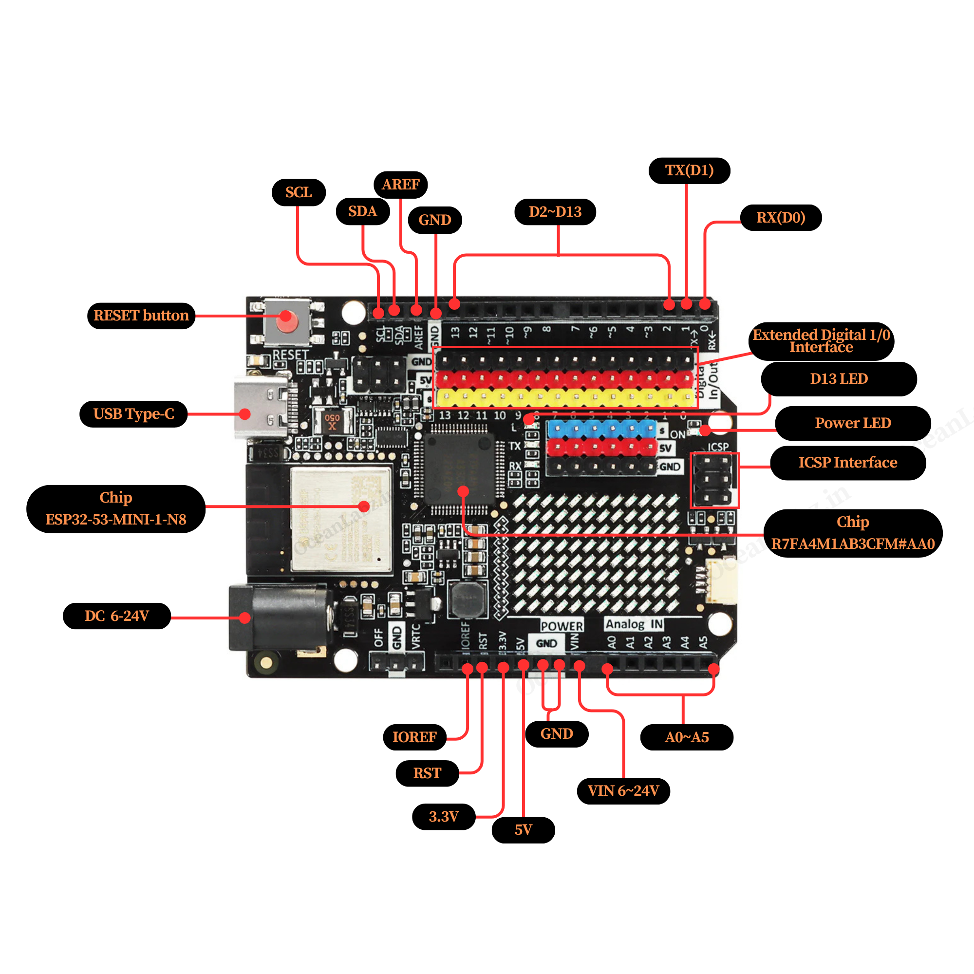
Hardware overview
| Arduino UNO R4 ESP32-S3 indication diagram |
 |
Programming the Arduino
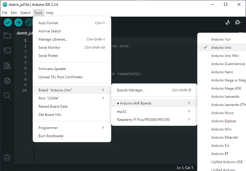
Step 1: Select your board type and port
- You’ll need to select the entry in the Tools > Board menu that corresponds to your Arduino board.
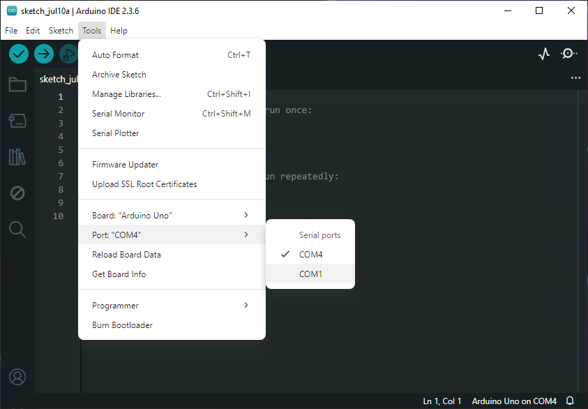
Select the serial device of the board from the Tools | Serial Port menu. This is likely to be COM4 or higher (COM1 and COM2 are usually reserved for hardware serial ports). To find out, you can disconnect your board and re-open the menu; the entry that disappears should be the Arduino board. Reconnect the board and select that serial port.
Step 2: Upload the program
- Copy the provided code into your Arduino IDE.
// Blink example
void setup() {
  pinMode(13, OUTPUT);
}

void loop() {
  digitalWrite(13, HIGH); // Turn the LED on (HIGH is the voltage level)
  delay(1000);                      // Wait for a second
  digitalWrite(13, LOW);  // Turn the LED off by making the voltage LOW
  delay(1000);                      // Wait for a second
}
Now, simply click the “Upload” button in the environment. Wait a few seconds – you should see the RX and TX leds on the board flashing. If the upload is successful, the message “Done uploading.” will appear in the status bar.
A few seconds after the upload finishes, you should see the pin 13 (L) LED on the board start to blink (in orange). If it does, congratulations! You’ve gotten Arduino up-and-running.