Index
Now it’s time to test another important part of our project: the 1.8-inch TFT display.
The TFT display gives your ESP32 a colorful graphical interface where you can show text, sensor readings, icons, menus, animations, and other visual information.
In this lesson, we will connect the 1.8-inch 128×160 ST7735 TFT display to the ESP32 using the SPI interface and run a simple test program to verify that the display is working correctly.
Why This Matters
Before using the TFT display in a larger project, it is important to make sure that the display, SPI communication, and wiring are working correctly.
If the display is not initialized properly, you may see a completely blank screen, incorrect colors, distorted graphics, or no response at all.
This lesson helps us confirm that the TFT display is working correctly before moving to the next stage of the project.
What You’ll Need
| Component | Purpose |
|---|---|
| 1.8-Inch TFT Display | Displays text and graphics |
| ESP32 Board | Controls the TFT display |
| Breadboard + Jumper Wires | For connections |
| USB Cable | To program and power the ESP32 |
Pinout
The 1.8-inch TFT uses the SPI communication protocol. The important pins are:
| TFT Pin | ESP32-S3/S3 Mini | ESP32 Pin | ESP32-C3 | Function |
|---|---|---|---|---|
| VCC | 3.3V | Power | ||
| GND | GND | Ground | ||
| SCL / CLK | GPIO 18 | SPI Clock | ||
| SDA / MOSI | GPIO 23 | SPI Data | ||
| CS | GPIO 5 | Chip Select | ||
| DC / A0 | GPIO 2 | Data/Command | ||
| RST | GPIO 4 | Reset | ||
| LED / BL | 3.3V | Backlight |
Note: Pin labels can vary slightly between TFT modules. Always check the labels printed on your display before making the connections.
What Is SPI?
SPI, or Serial Peripheral Interface, is a communication protocol commonly used by displays, sensors, memory cards, and other modules.
For our TFT display, SPI uses signals such as:
- SCK / CLK — SPI clock
- MOSI / SDA — Data sent from ESP32 to the display
- CS — Selects the TFT display
- DC — Tells the display whether the data is a command or display data
- RST — Resets the display
The ESP32 sends commands and graphical data to the TFT through these SPI connections.
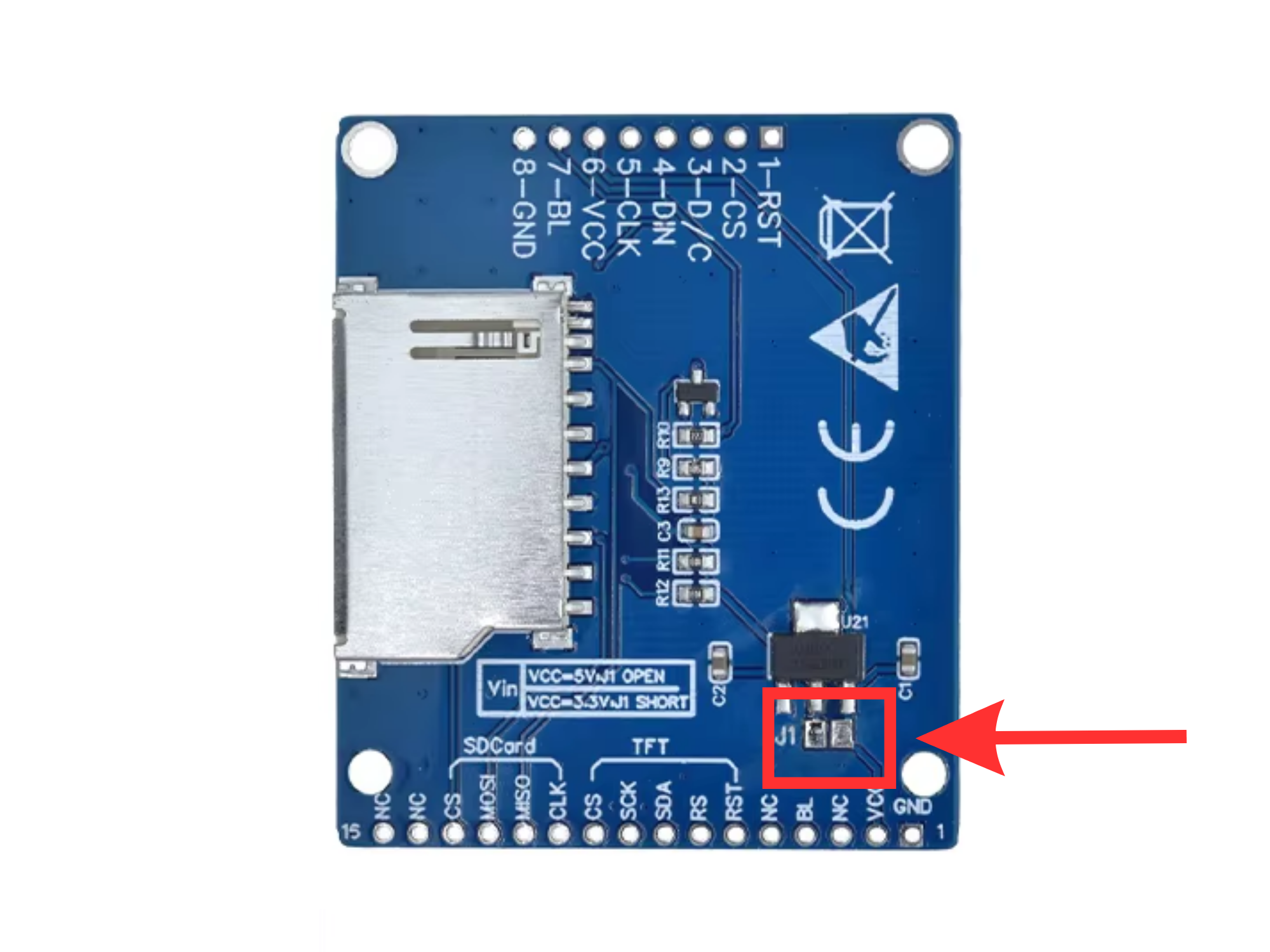
Important Note:
This TFT display has a 3.3V / 5V power selection point.
- If you want to power the display using 3.3V: first solder the 3.3V selection point on the display.
- If you want to power the display using 5V from the ESP32: do not solder the selection point. Leave it in its original, unsoldered condition.
Make sure to select the correct power option before connecting the display to your ESP32.
Flash Firmware (Browser-Based)
No Arduino IDE required — flash directly from your browser using Web Serial.
- Click “CONNECT” below
- Hold BOOT button on ESP32 and connect USB
- Select the ESP32 port and click Connect
- Choose “Install OceanLabz ESP32” and click Install
- Wait 2 minutes for completion