Index
Introduction
In this lesson, we will learn about the XNOR gate, which is the opposite of the XOR gate.
XNOR stands for Exclusive NOR.
An XNOR gate gives an output HIGH (1) when both inputs are the same.
Because it checks equality, it is commonly called an Equality Gate.
What Is an XNOR Gate?
An XNOR gate is a two-input logic gate.
Simple meaning:
Output is ON when Input A and Input B are equal.
- Both LOW → Output HIGH
- Both HIGH → Output HIGH
Truth Table of XNOR Gate
| Input A | Input B | Output |
|---|---|---|
| 0 | 0 | 1 |
| 0 | 1 | 0 |
| 1 | 0 | 0 |
| 1 | 1 | 1 |
Output is HIGH only when A = B.
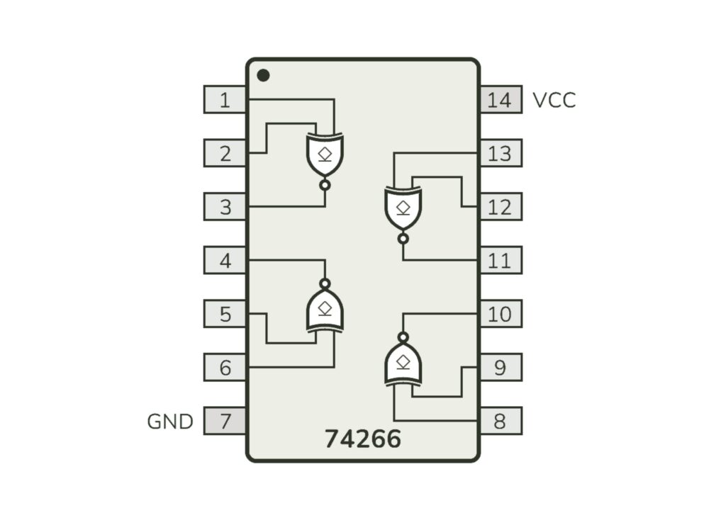
IC 74266 – Quad 2-Input XNOR Gate
IC 74266 contains four XNOR gates inside a single IC.
Key Features:
- 4 independent XNOR gates
- Operates at 5V
- TTL logic IC (74xx family)
- Suitable for comparison logic
IC 74266 Pin Configuration
| Pin | Function |
|---|---|
| 1 | Input A1 |
| 2 | Input B1 |
| 3 | Output Y1 |
| 4 | Output Y2 |
| 5 | Input A2 |
| 6 | Input B2 |
| 7 | GND |
| 8 | Input A3 |
| 9 | Input B3 |
| 10 | Output Y3 |
| 11 | Output Y4 |
| 12 | Input B4 |
| 13 | Input A4 |
| 14 | VCC (5V) |
Why Do We Use an XNOR Gate?
XNOR gates are used when:
- Equality check is required
- Data comparison is needed
- Verification logic is required
Real-life examples:
- Digital locks
- Data matching
- Error checking systems
Components Required
| Component | Quantity | Purpose |
|---|---|---|
| IC 74266 | 1 | XNOR logic |
| Push Buttons | 2 | Input control |
| 10k Resistor | 2 | Pull Down |
| LED | 1 | Output indication |
| 220Ω Resistor | 1 | LED protection |
| Breadboard | 1 | Circuit building |
| Jumper Wires | As required | Connections |
| 5V Power Supply | 1 | Power source |
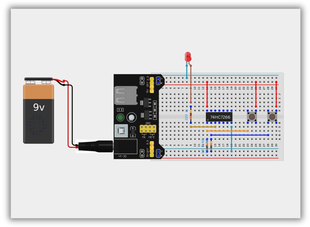
Circuit Diagram / Wiring
- Place IC 74266 on the breadboard
- Connect Pin 14 to +5V
- Connect Pin 7 to GND
- 10kΩ resistor from Pin 1 (Input A) → GND
- 10kΩ resistor from Pin 2 (Input B) → GND
- Connect Push Button A to Pin 1 (Input A)
- Connect Push Button B to Pin 2 (Input B)
- Connect Pin 3 (Output) to LED through 220Ω resistor
- Connect LED’s other end to GND
Working Principle
Case 1: Both Buttons OFF (0,0)
- Output = HIGH
- LED ON
Case 2: Inputs Different (1,0 or 0,1)
- Output = LOW
- LED OFF
Case 3: Both Buttons ON (1,1)
- Output = HIGH
- LED ON
This confirms XNOR gate operation.
Observation Table
| Button A | Button B | Output | LED |
|---|---|---|---|
| OFF | OFF | 1 | ON |
| ON | OFF | 0 | OFF |
| OFF | ON | 0 | OFF |
| ON | ON | 1 | ON |
Common Mistakes & Troubleshooting
❌ LED not ON when both buttons pressed
✔ Check input connections
❌ IC not responding
✔ Verify power supply
❌ Output unstable
✔ Avoid floating inputs
Real-Life Applications
- Digital comparison circuits
- Equality checking logic
- Data verification
- Error detection
- Security systems