Index
Introduction
In this lesson, we will learn about the XOR gate, one of the most interesting and useful logic gates in digital electronics.
XOR stands for Exclusive OR.
An XOR gate gives an output HIGH (1) only when the inputs are different.
This gate is widely used in:
- Comparison circuits
- Error detection
- Digital decision making
What Is an XOR Gate?
An XOR gate is a two-input logic gate.
Simple meaning:
Output is ON when inputs are NOT the same.
- One input ON → Output ON
- Both inputs same → Output OFF
Truth Table of XOR Gate
| Input A | Input B | Output |
|---|---|---|
| 0 | 0 | 0 |
| 0 | 1 | 1 |
| 1 | 0 | 1 |
| 1 | 1 | 0 |
Output is HIGH only when A ≠ B.
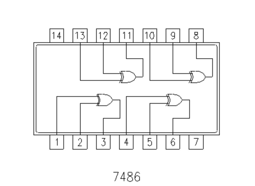
IC 7486 – Quad 2-Input XOR Gate
IC 7486 contains four XOR gates inside one IC.
Key Features:
- 4 independent XOR gates
- Works at 5V
- TTL logic IC (74xx family)
- Very common in digital systems
IC 7486 Pin Configuration
| Pin | Function |
|---|---|
| 1 | Input A1 |
| 2 | Input B1 |
| 3 | Output Y1 |
| 4 | Input A2 |
| 5 | Input B2 |
| 6 | Output Y2 |
| 7 | GND |
| 8 | Output Y3 |
| 9 | Input A3 |
| 10 | Input B3 |
| 11 | Output Y4 |
| 12 | Input A4 |
| 13 | Input B4 |
| 14 | VCC (5V) |
Why Do We Use an XOR Gate?
XOR gates are used when:
- Difference between two signals is needed
- Comparison logic is required
- Error detection is required
Real-life example:
- Two switches controlling a staircase light
- Password comparison
- Parity checking in data transmission
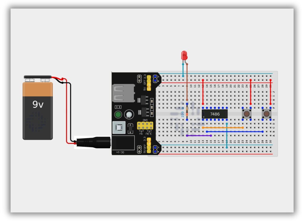
Components Required
| Component | Quantity | Purpose |
|---|---|---|
| IC 7486 | 1 | XOR logic |
| Push Buttons | 2 | Input control |
| LED | 1 | Output indication |
| 220Ω Resistor | 1 | LED protection |
| Breadboard | 1 | Circuit building |
| Jumper Wires | As required | Connections |
| 5V Power Supply | 1 | Power source |
Circuit Diagram / Wiring
- Place IC 7486 on the breadboard
- Connect Pin 14 to +5V
- Connect Pin 7 to GND
- Connect Push Button A to Pin 1 (Input A)
- Connect Push Button B to Pin 2 (Input B)
- Connect Pin 3 (Output) to LED through 220Ω resistor
- Connect LED’s other end to GND
Working Principle
Case 1: Both Buttons OFF (0,0)
- Output = LOW
- LED OFF
Case 2: Only One Button ON (1,0 or 0,1)
- Output = HIGH
- LED ON
Case 3: Both Buttons ON (1,1)
- Output = LOW
- LED OFF
This confirms XOR logic behavior.
Observation Table
| Button A | Button B | Output | LED |
|---|---|---|---|
| OFF | OFF | 0 | OFF |
| ON | OFF | 1 | ON |
| OFF | ON | 1 | ON |
| ON | ON | 0 | OFF |
Common Mistakes & Troubleshooting
❌ LED not glowing when one button pressed
✔ Check input wiring
❌ LED always OFF
✔ Check VCC and GND connections
❌ IC output unstable
✔ Inputs may be floating
Real-Life Applications
- Staircase wiring
- Parity generators
- Digital comparison circuits
- Error detection systems
- Cryptography basics