Index
Introduction
In this lesson, we will learn about the NAND gate, one of the most important logic gates in digital electronics.
A NAND gate is the inverse of the AND gate.
It gives an output LOW (0) only when ALL inputs are HIGH.
For all other input combinations, the output is HIGH.
The NAND gate is called a Universal Gate because any logic gate can be built using only NAND gates.
What Is a NAND Gate?
A NAND gate is a two-input logic gate.
Simple meaning:
Output is OFF only if Input A AND Input B are ON.
This makes NAND logic very powerful and flexible.
Truth Table of NAND Gate
| Input A | Input B | Output |
|---|---|---|
| 0 | 0 | 1 |
| 0 | 1 | 1 |
| 1 | 0 | 1 |
| 1 | 1 | 0 |
Output is LOW only when both inputs are HIGH.
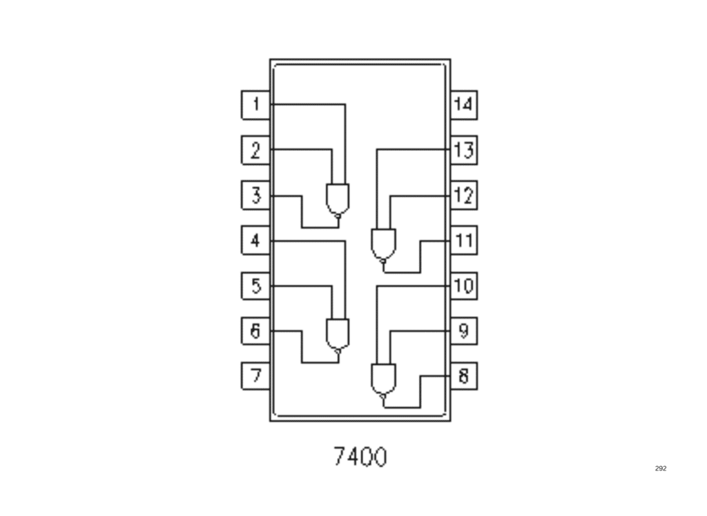
IC 7400 – Quad 2-Input NAND Gate
IC 7400 contains four NAND gates inside a single IC.
Key Features:
- 4 independent NAND gates
- Operates at 5V
- TTL logic IC (74xx family)
- Very common in digital and control circuits
IC 7400 Pin Configuration
| Pin | Function |
|---|---|
| 1 | Input A1 |
| 2 | Input B1 |
| 3 | Output Y1 |
| 4 | Input A2 |
| 5 | Input B2 |
| 6 | Output Y2 |
| 7 | GND |
| 8 | Output Y3 |
| 9 | Input A3 |
| 10 | Input B3 |
| 11 | Output Y4 |
| 12 | Input A4 |
| 13 | Input B4 |
| 14 | VCC (5V) |
Why Is NAND Gate Called Universal?
Using only NAND gates, we can create:
- NOT gate
- AND gate
- OR gate
- XOR gate
This is why NAND is widely used in IC design and digital systems.
Components Required
| Component | Quantity | Purpose |
|---|---|---|
| IC 7400 | 1 | NAND logic |
| Push Buttons | 2 | Input control |
| LED | 1 | Output indication |
| 220Ω Resistor | 1 | LED protection |
| 10K Resistor | 2 | Input control |
| Breadboard | 1 | Circuit building |
| Jumper Wires | As required | Connections |
| 5V Power Supply | 1 | Power source |
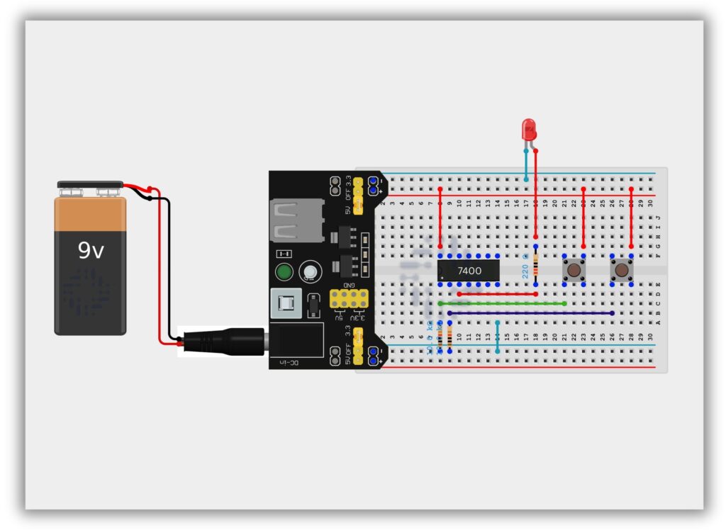
Circuit Diagram / Wiring
- Place IC 7400 on the breadboard
- Connect Pin 14 to +5V
- Connect Pin 7 to GND
- 10kΩ resistor from Pin 1 (Input A) → GND
- 10kΩ resistor from Pin 2 (Input B) → GND
- Connect Push Button 1 to Pin 1 (Input A)
- Connect Push Button 2 to Pin 2 (Input B)
- Connect Pin 3 (Output) to LED through 220Ω resistor
- Connect LED’s other end to GND
Working Principle
Case 1: Both Buttons NOT Pressed (0,0)
- Output = HIGH
- LED ON
Case 2: Only One Button Pressed (1,0 or 0,1)
- Output = HIGH
- LED ON
Case 3: Both Buttons Pressed (1,1)
- Output = LOW
- LED OFF
This confirms NAND gate logic.
Observation Table
| Button A | Button B | Output | LED |
|---|---|---|---|
| OFF | OFF | 1 | ON |
| ON | OFF | 1 | ON |
| OFF | ON | 1 | ON |
| ON | ON | 0 | OFF |
Common Mistakes & Troubleshooting
❌ LED never turns OFF
✔ Check if both inputs are actually HIGH
❌ IC overheating
✔ Verify power supply polarity
❌ Unstable output
✔ Avoid floating inputs (use pull-downs if needed)
Real-Life Applications
- Digital IC design
- Control logic
- Security systems
- Microprocessor architecture
- Alarm circuits