Index
Introduction
In this lesson, we will learn about the AND gate, one of the most important logic gates in digital electronics.
An AND gate gives an output HIGH (1) only when ALL its inputs are HIGH.
If any one input is LOW, the output becomes LOW.
This lesson will help you understand:
- How multiple inputs control a single output
- How IC 7408 works
- How to build a practical AND gate circuit using push buttons and an LED
What Is an AND Gate?
An AND gate is a two-input logic gate.
Simple meaning:
Output is ON only if Input A AND Input B are ON.
Real-life example:
- A machine starts only when Power switch AND Safety switch are ON
- A door opens only when Password AND Fingerprint are correct
Truth Table of AND Gate
| Input A | Input B | Output |
|---|---|---|
| 0 | 0 | 0 |
| 0 | 1 | 0 |
| 1 | 0 | 0 |
| 1 | 1 | 1 |
Output is HIGH only when both inputs are HIGH.
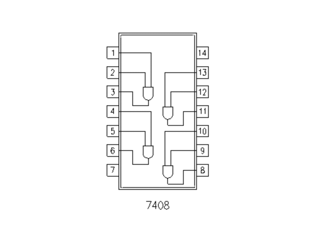
IC 7408 – Quad 2-Input AND Gate
IC 7408 contains four AND gates inside a single IC.
Key Features:
- 4 independent AND gates
- Operates at 5V
- TTL logic IC (74xx family)
- Very common in digital circuits
5. IC 7408 Pin Configuration
| Pin | Function |
|---|---|
| 1 | Input A1 |
| 2 | Input B1 |
| 3 | Output Y1 |
| 4 | Input A2 |
| 5 | Input B2 |
| 6 | Output Y2 |
| 7 | GND |
| 8 | Output Y3 |
| 9 | Input A3 |
| 10 | Input B3 |
| 11 | Output Y4 |
| 12 | Input A4 |
| 13 | Input B4 |
| 14 | VCC (5V) |
Why Do We Use an AND Gate?
AND gates are used when:
- Multiple conditions must be satisfied
- Safety logic is required
- Permission-based control is needed
Example uses:
- Industrial safety systems
- Password verification
- Digital decision making
7. Components Required
| Component | Quantity | Purpose |
|---|---|---|
| IC 7408 | 1 | AND logic |
| Push Buttons | 2 | Input control |
| LED | 1 | Output indication |
| 220Ω Resistor | 1 | LED protection |
| 10K Resistor | 2 | Input control |
| Breadboard | 1 | Circuit building |
| Jumper Wires | As required | Connections |
| 5V Power Supply | 1 | Power source |
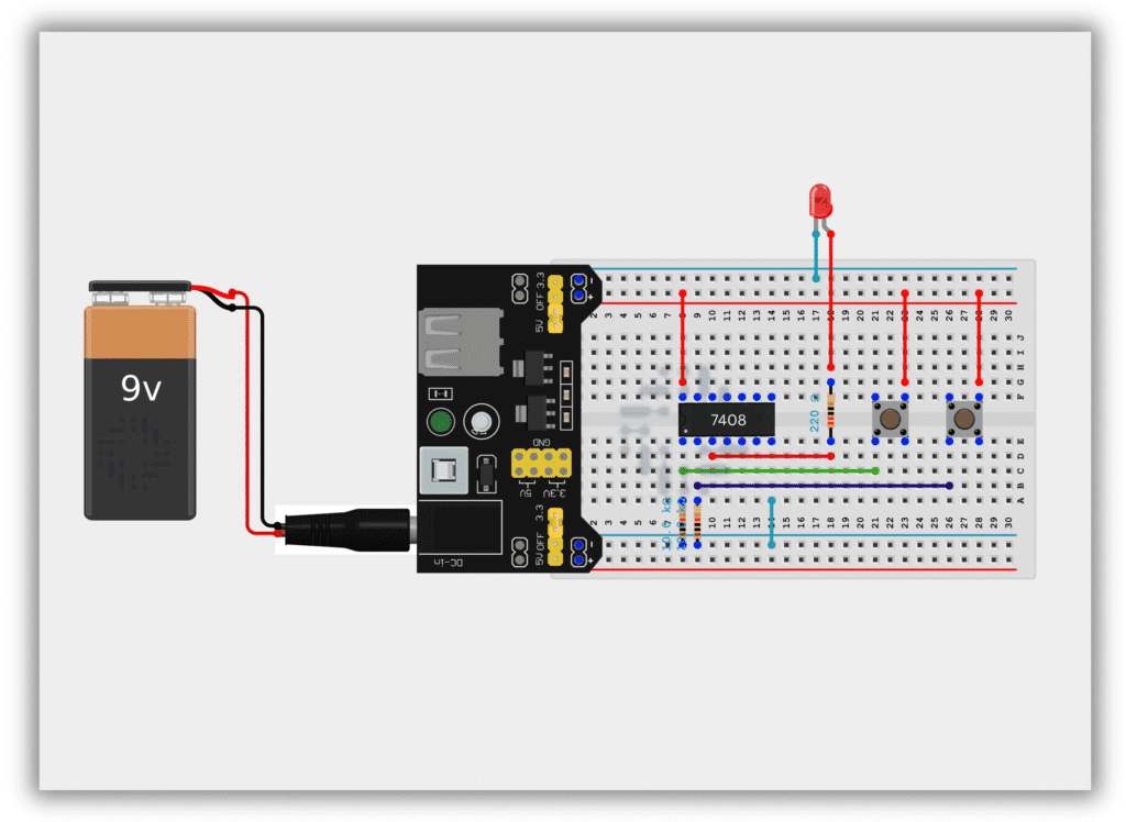
Circuit Diagram / Wiring
- Place IC 7408 on the breadboard
- Connect Pin 14 to +5V
- Connect Pin 7 to GND
- 10kΩ resistor from Pin 1 (Input A) → GND
- 10kΩ resistor from Pin 2 (Input B) → GND
- Connect Push Button 1 to Pin 1 (Input A)
- Connect Push Button 2 to Pin 2 (Input B)
- Connect Pin 3 (Output) to LED through 220Ω resistor
- Connect LED’s other end to GND
Working Principle
Case 1: No Button Pressed (0,0)
- Output = LOW
- LED OFF
Case 2: Only One Button Pressed (1,0 or 0,1)
- Output = LOW
- LED OFF
Case 3: Both Buttons Pressed (1,1)
- Output = HIGH
- LED ON
This confirms the AND gate logic.
Observation Table
| Button A | Button B | Output | LED |
|---|---|---|---|
| OFF | OFF | 0 | OFF |
| ON | OFF | 0 | OFF |
| OFF | ON | 0 | OFF |
| ON | ON | 1 | ON |
Common Mistakes & Troubleshooting
❌ LED never turns ON
✔ Check both input buttons
❌ LED always ON
✔ Inputs may be shorted to 5V
❌ IC not working
✔ Check Pin 14 (VCC) and Pin 7 (GND)
Real-Life Applications
- Security systems
- Voting machines
- Digital locks
- Control panels
- Logic decision circuits