Index
Introduction
In this lesson, we will learn about the NOT gate, which is the most basic logic gate in digital electronics.
A NOT gate is also called a Logic Inverter because it gives the opposite output of the input.
If the input is HIGH (1) → output becomes LOW (0)
If the input is LOW (0) → output becomes HIGH (1)
This lesson will help you understand:
- What logic inversion means
- How the IC 7404 works
- How to build a NOT gate circuit on a breadboard
What Is a NOT Gate?
A NOT gate is a single-input logic gate.
It simply inverts the input signal.
In simple words:
- ON becomes OFF
- OFF becomes ON
That is why it is called an Inverter.
Truth Table of NOT Gate
| Input (A) | Output (Y) |
|---|---|
| 0 (LOW) | 1 (HIGH) |
| 1 (HIGH) | 0 (LOW) |
The truth table clearly shows that the output is always the opposite of the input.
IC 7404 – Hex NOT Gate IC
IC 7404 is called a Hex NOT Gate, which means six NOT gates are available inside one IC.
Key Features of IC 7404:
- Contains 6 independent NOT gates
- Works on 5V power supply
- Part of the 74xx TTL logic family
- Very popular and beginner-friendly
IC 7404 Pin Configuration
| Pin Number | Function |
|---|---|
| 1 | Input A1 |
| 2 | Output Y1 |
| 3 | Input A2 |
| 4 | Output Y2 |
| 5 | Input A3 |
| 6 | Output Y3 |
| 7 | GND |
| 8 | Output Y4 |
| 9 | Input A4 |
| 10 | Output Y5 |
| 11 | Input A5 |
| 12 | Output Y6 |
| 13 | Input A6 |
| 14 | VCC (5V) |
Why Do We Use a NOT Gate?
NOT gates are used when we need:
- Signal inversion
- Active-LOW logic
- Enable / disable control
- Opposite decision making in digital circuits
Example:
- If a sensor is OFF → turn ON an alarm
- If a switch is released → LED should glow
Components Required
| Component | Quantity | Purpose |
|---|---|---|
| IC 7404 | 1 | Logic inversion |
| LED | 1 | Output indication |
| 220Ω Resistor | 1 | LED protection |
| Push Button | 1 | Input control |
| Breadboard | 1 | Circuit building |
| Jumper Wires | As required | Connections |
| 5V Power Supply | 1 | Power source |
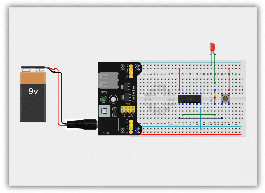
Circuit Diagram / Wiring
- Insert IC 7404 on the breadboard
- Connect Pin 14 to +5V
- Connect Pin 7 to GND
- Connect push button output to Pin 1 (Input)
- Connect Pin 2 (Output) to LED through a 220Ω resistor
- Connect LED’s other end to GND
Working Principle
Case 1: Button NOT Pressed (Input = LOW)
- Input is LOW (0)
- NOT gate output becomes HIGH (1)
- LED turns ON
Case 2: Button Pressed (Input = HIGH)
- Input becomes HIGH (1)
- NOT gate output becomes LOW (0)
- LED turns OFF
This proves that the output is always the inverse of the input.
Observation Table
| Button State | Input | Output | LED Status |
|---|---|---|---|
| Released | 0 | 1 | ON |
| Pressed | 1 | 0 | OFF |
Common Mistakes & Troubleshooting
❌ LED always ON
✔ Input pin may be floating – check grounding
❌ IC becomes hot
✔ Check VCC and GND connections
❌ LED not glowing
✔ Check LED polarity and resistor value
Real-Life Applications
- Automatic lighting systems
- Alarm and security circuits
- Logic signal conditioning
- Digital control systems
- Sensor-based applications