Index
Introduction
The ESP32-S3 WROOM N16R8 CAM Dev Board is a powerful microcontroller module with built-in Wi-Fi, Bluetooth, and camera support. It features a dual-core processor, 16MB Flash, and 8MB PSRAM for advanced AI and IoT applications. With its onboard USB, OV2640 camera interface, and rich GPIO support, it’s ideal for machine vision and smart automation. This guide will help you set up and start using the board quickly.
| Feature | Details |
|---|---|
| Chipset | ESP32-S3 (dual-core 32-bit Xtensa LX7 @ 240MHz) |
| Flash Memory | 16MB (QSPI) |
| PSRAM | 8MB |
| Wireless | Wi-Fi 802.11 b/g/n (2.4 GHz), Bluetooth 5 (LE) |
| USB Support | Native USB OTG + USB-to-Serial (Dual USB-C) |
| Camera Support | OV2640 Camera Module (with dedicated header) |
| GPIOs | Rich GPIO availability with ADC, PWM, I2C, SPI, UART |
| Operating Voltage | 3.3V logic level (5V input via USB-C) |
| Power Supply | USB-C, external 5V via VIN |
| AI Acceleration | Vector instructions for neural network processing |
| Programming Support | Arduino IDE, ESP-IDF, MicroPython |
Features
- Built for AI & Vision Projects: Supports edge AI processing with camera input for applications like face detection, motion sensing, and object tracking.
- Camera-Ready: Includes an OV2640 camera header, making it ideal for video streaming and surveillance applications.
- Dual USB-C Ports: Simplifies programming and OTG communication with separate ports for power/programming and USB-host use.
- Seamless Wireless Connectivity: Integrated Wi-Fi and Bluetooth 5 enable fast, wireless communication with cloud servers, phones, or other IoT devices.
- Rich I/O Options: Easily connect sensors, relays, displays, and other peripherals through standard interfaces like I2C, SPI, UART, ADC, and PWM.
- Flexible Power Input: Supports 5V–16V input for use in battery or solar-powered projects.
- Cross-Platform Support: Program using Arduino IDE, ESP-IDF, or MicroPython, depending on your preference and project complexity.
Onboard SD Card Support
- Built-in microSD card slot available on the board (just like ESP32-CAM).
- Supports saving captured camera images or video frames directly to SD card.
- Ideal for image logging, data storage, and offline recording.
- Compatible with standard FAT file systems using Arduino SD and FS libraries.
Applications
- Face detection and image capture
- Smart security and door monitoring
- IoT cloud-based monitoring
- Offline image/data logging to SD card
- AI at the edge (object tracking, gesture detection)
- Wireless camera streaming
- QR/barcode recognition
- Smart farming and automation
- Educational AI + IoT kits
- Prototype vision-based projects
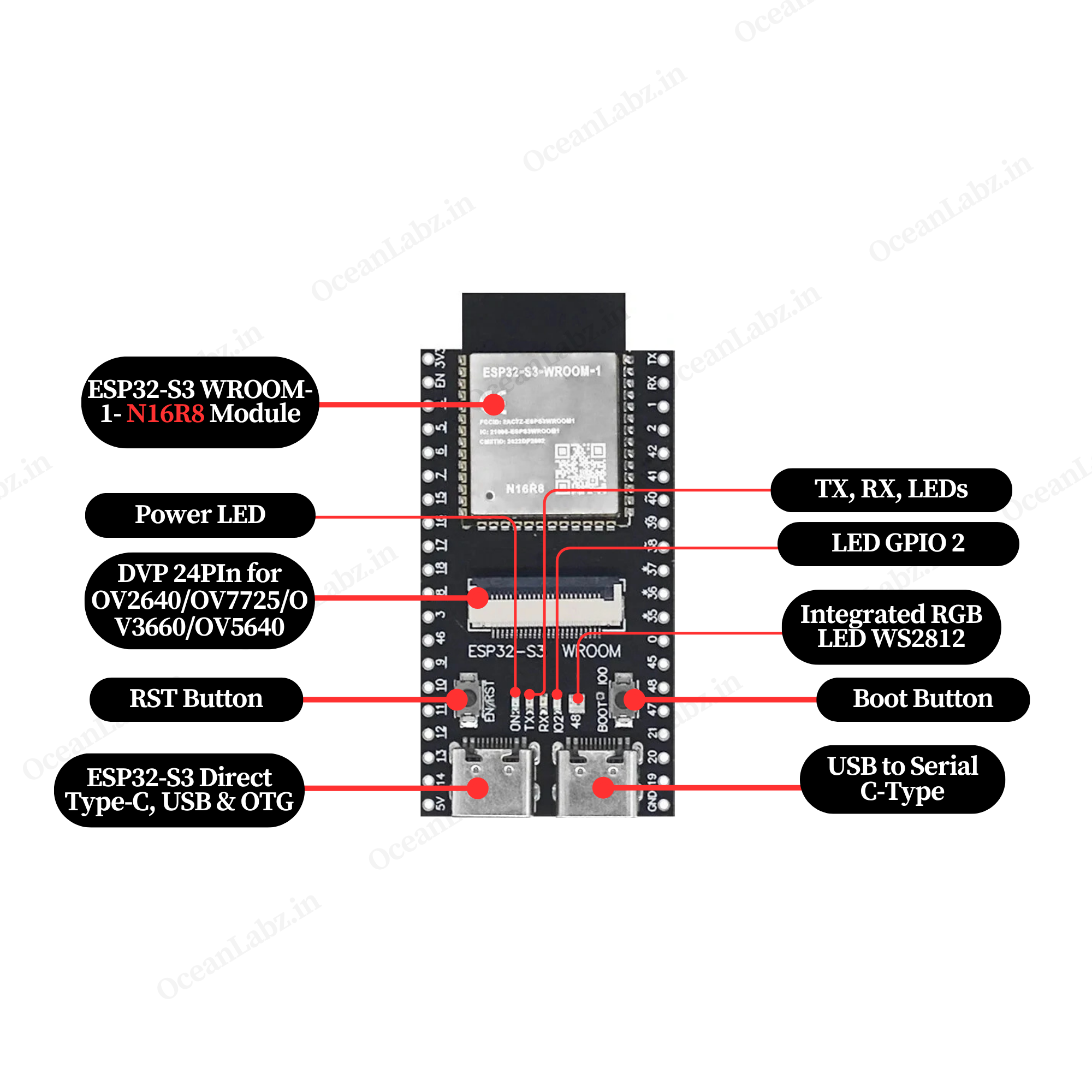
Hardware overview
| ESP32-S3 DevKit-N16R8 CAM indication diagram front |
 |
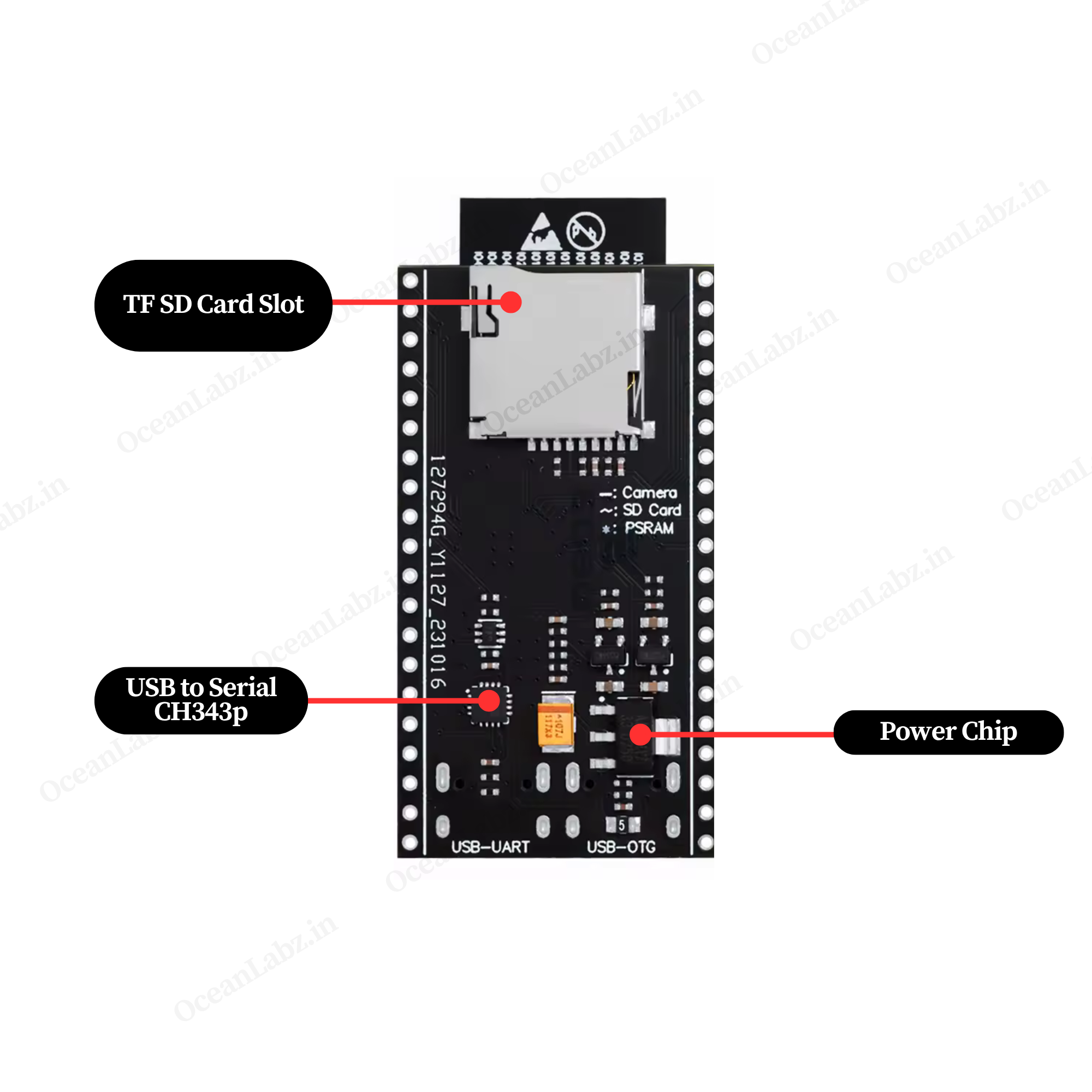
| ESP32-S3 DevKit-N16R8 CAM indication diagram Back |
 |
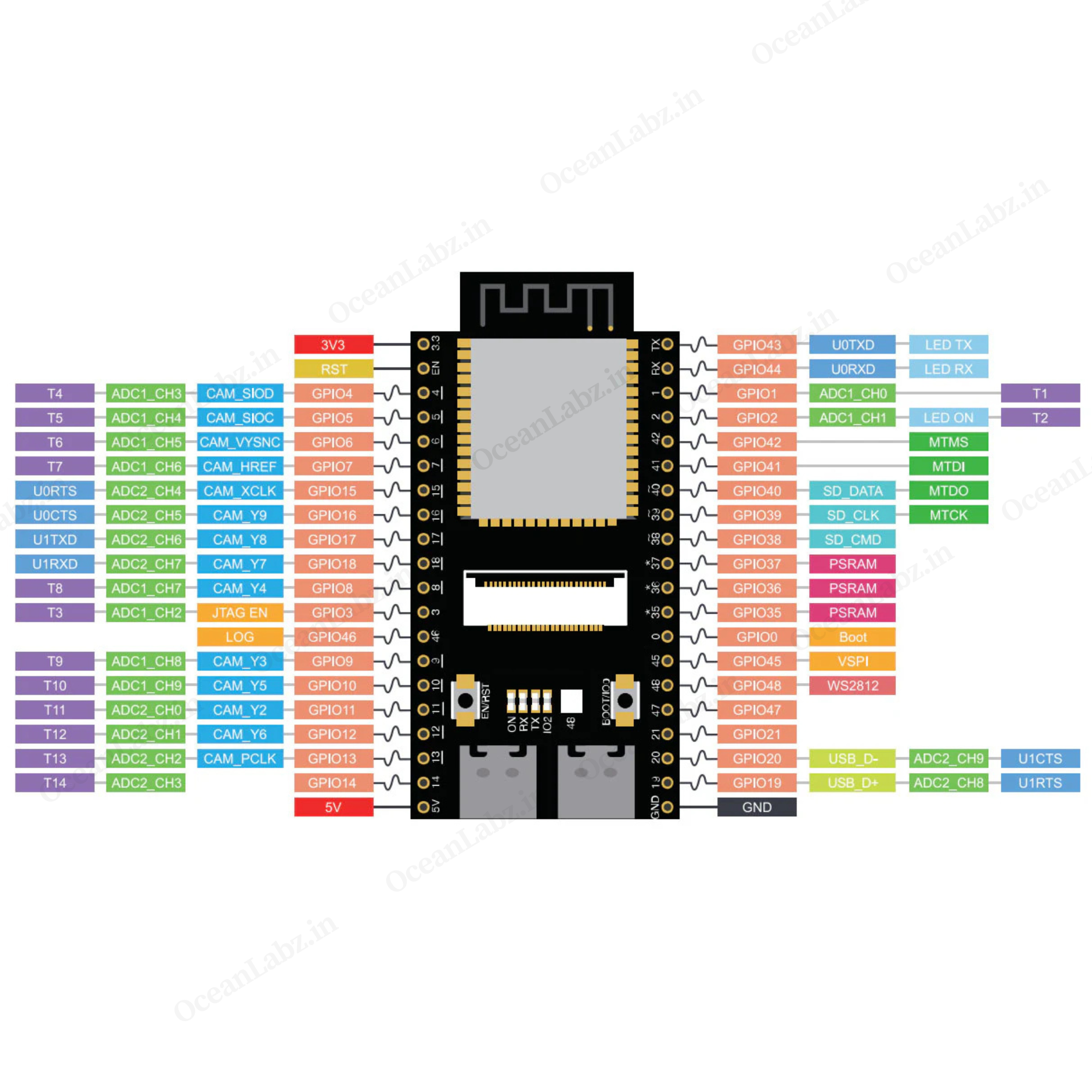
| ESP32-S3 DevKit-N16R8 CAM Pinout Diagram |
 |
Getting Started
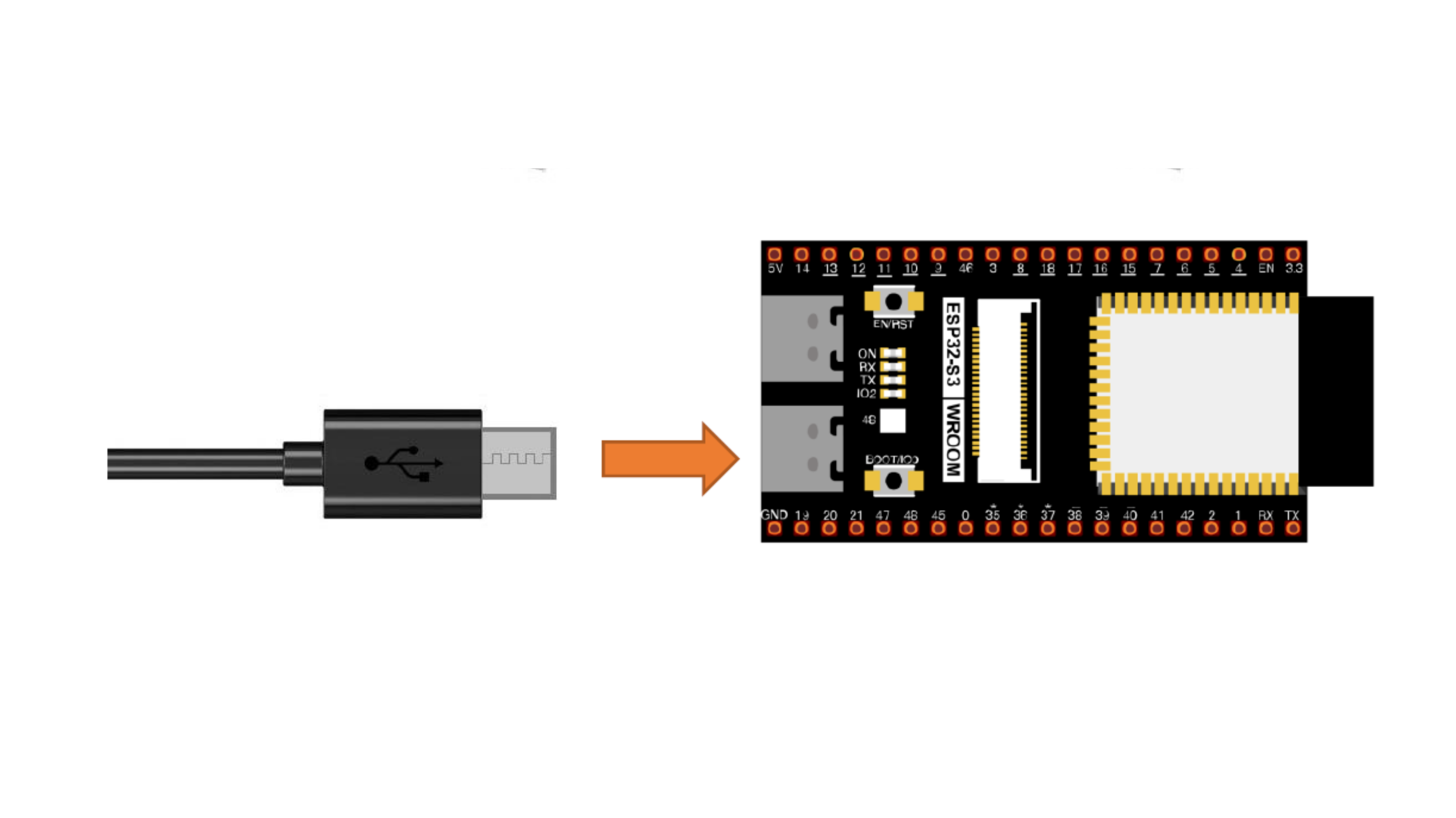
Hardware Preparation
To begin working with the ESP32-S3 DevKit-N16R8 CAM, ensure you have the following:
- ESP32-S3 DevKit-N16R8 CAM Development Board
- USB Type-C Cable
- Computer with Windows, macOS, or Linux operating system.
Software Preparation
Install Arduino IDE:
- Download and install the latest version of the Arduino IDE.
Add ESP32 Board Support:
- Open Arduino IDE and navigate to
File>Preferences.

- In the “Additional Boards Manager URLs” field, enter:
https://raw.githubusercontent.com/espressif/arduino-esp32/gh-pages/package_esp32_index.json

- Click
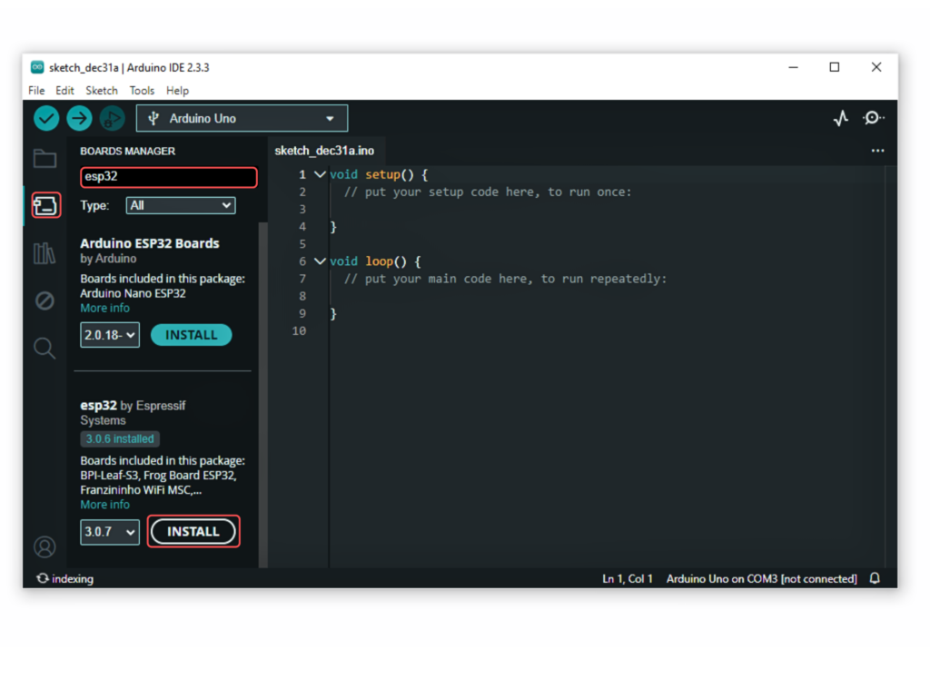
OK. - Go to the “Board manager” tab on the left-hand side of the screen.
- Click on the “Board Manager” button (Board icon) at the top of the Board tab.
- In the Board Manager window, type “esp32” in the search bar.
- Locate the “esp32” library click on the “Install” button next to it.
- Wait for the board to be installed.
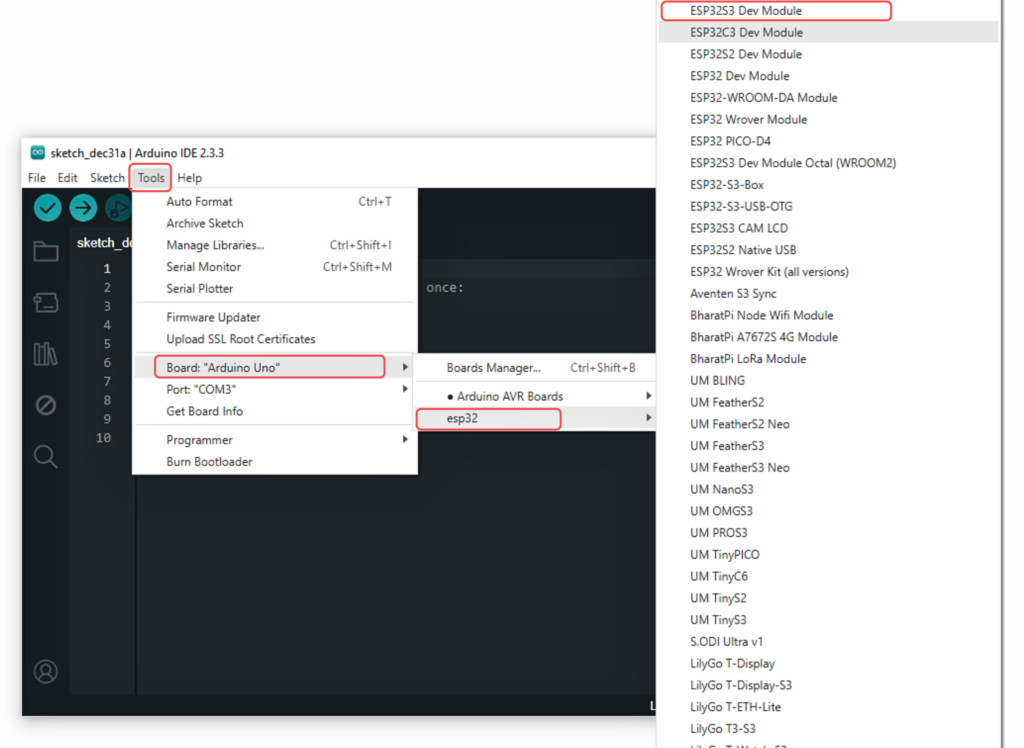
Select the ESP32-S3 Dev Module:
In Arduino IDE, go to Tools > Board and select “ESP32S3 Dev Module” or the appropriate option for your module.
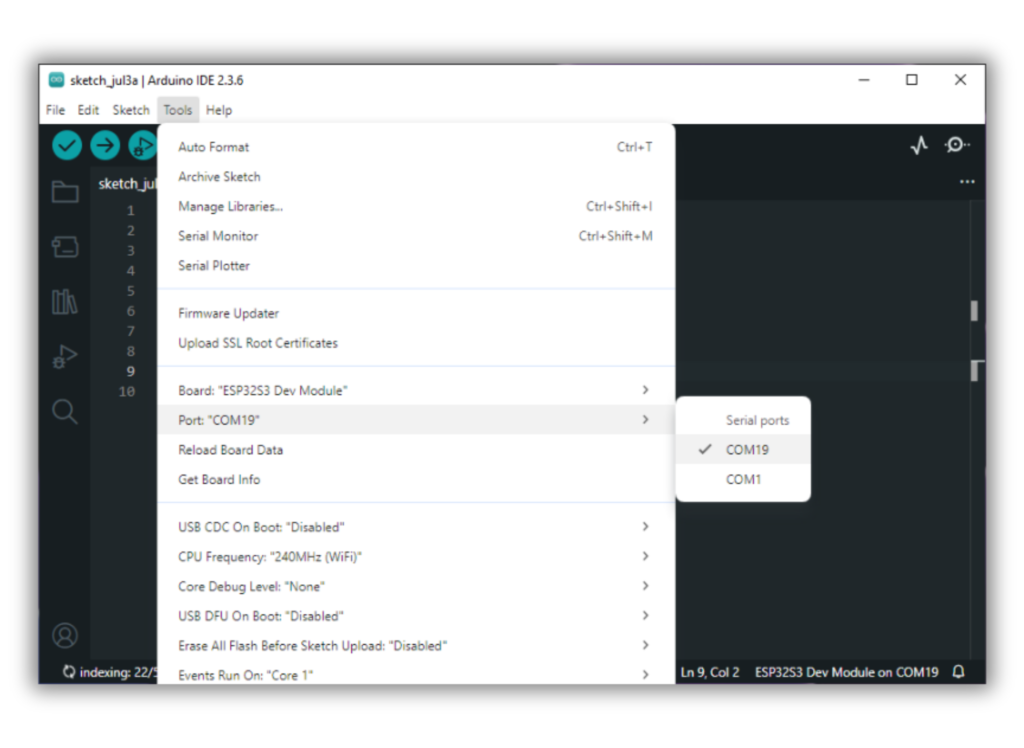
Now, connect the ESP32S3 Dev Module to your computer using a USB cable. Then, go to Tools > Port and select the COM port that the ESP32S3 Dev Module is connected to.
Running Your First Program
Let’s upload a simple “Blink” program to test the setup:
- Open the Blink Example:
- In Arduino IDE, go to
File>Examples>01.Basics>Blink.
- In Arduino IDE, go to

- Upload the Program:
- Click the
Uploadbutton. - Once uploaded, the onboard LED should start blinking, indicating a successful upload.
- Click the

Comments (2)